
Grand Cherokee 4WD L6-242 4.0L VIN S MFI (1993)
Hydraulic Control Assembly - Antilock Brakes: Description and Operation
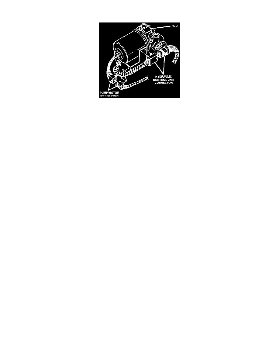
Hydraulic Control Unit
The Hydraulic Control Unit (HCU) contains the valve block assembly and the pump/motor assembly.
VALVE BLOCK ASSEMBLY
The valve block assembly contains six valve/solenoids with three inlet valves and three outlet valves. The inlet valves are spring-loaded in the
open position and the outlet valves are spring-loaded in the closed position. During an antilock stop, these valves are cycled to maintain the proper
slip ratio for each channel. If a wheel locks, the inlet valve is closed to prevent any further pressure increase. Then the outlet valve is opened to
release the pressure back to the reservoir until the wheel is no longer slipping. Once the wheel is no longer slipping, the outlet valve is closed and
the inlet valve is opened to reapply pressure. If the wheel is decelerating within its predetermined limits (proper slip ratio), both valves will close
to hold the pressure constant. During the stop, the build pressure is initially supplied by the master cylinder. When the build pressure is reapplied,
fluid comes from the master cylinder, which causes the brake pedal to drop. The pedal continues to drop until the pedal travel sensor signals the
Controller, Anti-lock Brake (CAB) to turn on the pump/motor. The pump/motor then pumps fluid from the reservoir into the brake system. The
master cylinder pistons and brake pedal are then moved back until the pedal travel sensor signals the CAB to turn off the pump/motor.
PUMP/MOTOR ASSEMBLY
The pump/motor assembly provides the extra volume of fluid needed during antilock braking. The pump is connected to the master cylinder
reservoir by supply and return hoses.
The pump is operated by an integral electric motor. This DC-type motor is controlled by the CAB.
The pump mechanism consists of two opposing pistons operated by an eccentric cam. One piston supplies the primary hydraulic circuit. The
opposite piston supplies the secondary hydraulic circuit. In operation, one piston draws fluid from the master cylinder reservoir. The opposing
piston then pumps fluid to the valve body solenoids. The pump cam is operated by the electric motor. The rotation sensor is an inductive pick-up
used by the CAB to monitor pump/motor operation.