
Grand Cherokee 4WD L6-242 4.0L VIN S MFI (1993)
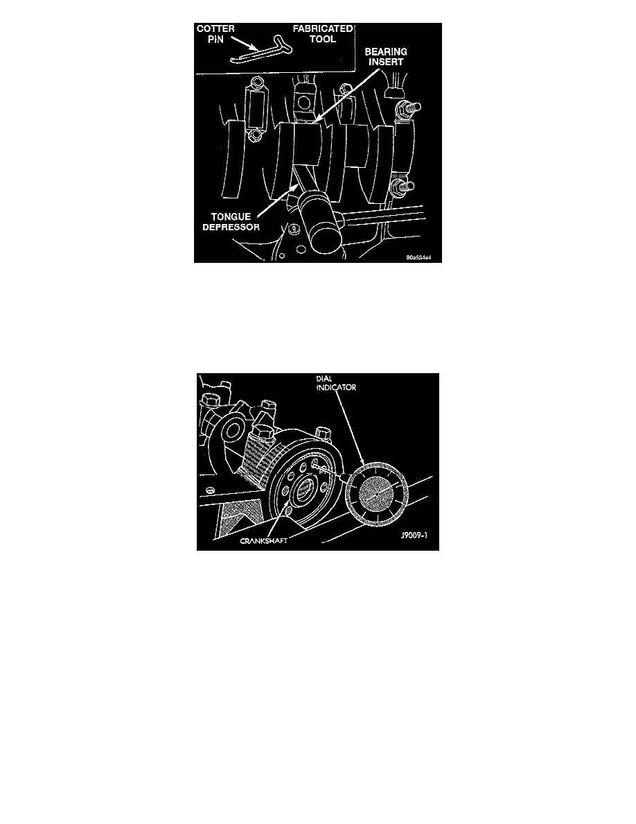
8. Remove the upper insert by LOOSENING (DO NOT REMOVE) all of the other bearing caps. Now insert a small cotter pin tool in the crankshaft
journal oil hole. Bend the cotter pin as illustrated to fabricate the tool. With the cotter pin tool in place, rotate the crankshaft so that the upper bearing
insert will rotate in the direction of its locking tab. Because there is no hole in the No. 3 main journal, use a tongue depressor or similar soft-faced
tool to remove the bearing insert. After moving the insert approximately 25 mm (1 inch), it can be removed by applying pressure under the tab.
9. Using the same procedure described above, remove the remaining bearing inserts one at a time for inspection.
Installation
1. Lubricate the bearing surface of each insert with engine oil.
2. Loosen all the main bearing caps. Install the main bearing upper inserts.
3. Install the lower bearing inserts into the main bearing caps.
4. Install the main bearing cap(s) and lower insert(s).
5. Tighten the bolts of caps 1, 2, 4, 5, 6, and 7 to 54 Nm (40 ft. lbs.) torque. Now tighten these bolts to 95 Nm (70 ft. lbs.) torque. Finally, tighten
these bolts to 108 Nm (80 ft. lbs.) torque.
6. Push the crankshaft forward and backward. Load the crankshaft front or rear and tighten cap bolt No. 3 to 54 Nm (40 ft. lbs.) torque. Then tighten
to 95 Nm (70 ft. lbs.) torque and finally tighten to 108 Nm (80 ft. lbs.) torque.
7. Rotate the crankshaft after tightening each main bearing cap to ensure the crankshaft rotates freely.
8. Check crankshaft end play. Crankshaft end play is controlled by the thrust bearing which is flange and installed at the No. 2 main bearing position.
a. Attach a magnetic base dial indicator to the cylinder block at either the front or rear of the engine.
b. Position the dial indicator rod so that it is parallel to the center line of the crankshaft.
c. Pry the crankshaft forward, position the dial indicator to zero.
d. Pry the crankshaft forward and backward. Note the dial indicator readings. End play is the difference between the high and low measurements.
Correct end play is 0.038 - 0.165 mm (0.0015 - 0.0065 inch). The desired specifications are 0.051 - 0.064 mm (0.002 - 0.0025 inch).
e. If end play is not within specification, inspect crankshaft thrust faces for wear. If no wear is apparent, replace the thrust bearing and measure end
play. If end play is still not within specification, replace the crankshaft.
9. If the crankshaft was removed, install the crankshaft into the cylinder block.
10. Install main bearing cap brace tighten nuts to 47 Nm (35 ft. lbs.) torque.
11. Install oil pump assembly. and tighten attaching bolts to 23 Nm (17 ft. lbs.).