
Grand Cherokee 4WD L6-242 4.0L VIN S MFI (1993)
2.
Partially remove the handle and disconnect the release rod and power lock actuator rod if applicable. Remove the handle assembly. Retain the lock
cylinder for installation with the new handle assembly.
3.
Manually pull the release rod to unlatch the liftgate.
4.
Remove the interior trim as described in the Service Manual No. 81-370-2147.
5.
Install the liftgate lock cylinder pushing it into the back of the handle, making certain it is fully seated. When installing the lock cylinder, push on
the die cast housing, not on the lock cylinder mechanisms. (There should be no gap between the cylinder and the handle when viewed from the
outside of the handle.)
6.
Move the key cylinder lever to the right (passenger side) when the handle is orientated in the installed position and at the same time lower the slide
handle so the key cylinder lever can engage over the slide lever stud. Take care not to cut or remove the small anti-rattle washer that is on the slide
lever stud. This washer should be outboard of the key cylinder lever when installed.
7.
On vehicles with power door locks, install the black clip on the end of the slide and insert the lock actuator rod in the clip.
8.
Install the power lock actuator rod.
9.
On vehicles without power door locks, install the special screw clip.
10.
Apply Mopar Lubriplate (PN 4549615) on the slide lever to minimize the sliding effort. With the handle in the unlocked position, (lever is as far
left as viewed from the back of the vehicle or to the passenger side of the vehicle) install the right side of the handle and then the left side. Slide
the handle as far to the right as possible and hold it while installing the retaining nut. Tighten the nut to 45 in.lbs. (4.9 N-m). Check the handle to
be sure it is secure.
11.
With the handle lever in the unlocked position, firmly press the latch release rod into the metal clip on the slide lever. Do not pull up on the rod
when loading, but allow it to be in a relaxed position when installing it into the clip. With the liftgate in the open position, verify that the
lock/unlock functions operate properly.
NOTE:
DO NOT CLOSE THE LIFTGATE AT THIS TIME. IF NOT PREVIOUSLY DONE, CHECK THE SIZE OF THE HEAD ON THE LIFTGATE
STRIKER ASSEMBLY FASTENERS. IF THE FASTENER HEADS ARE SMALLER THAN 11/16 IN. (18 MM), REPLACE THE STRIKER
ASSEMBLY. REFER TO THE "STRIKER WITH SEAL PLATE INSTALLATION" PROCEDURE.
12.
If not previously done, check the liftgate actuator operation and if it is slow or sluggish, replace the actuator with PN 55154745.
13.
Install the trim panel as described in the Grand Cherokee Service Manual No. 81-370-2147.
Striker With Seal Plate Installation
1.
Remove the two retaining nuts from the liftgate striker and remove the striker assembly.
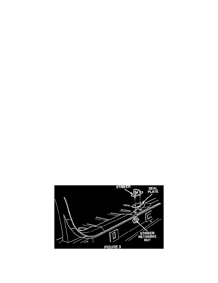
2.
Assemble the new striker-to-seal plate with the foam seal facing down (Figure 3). The straight side of the seal plate faces the rear of the vehicle as
does the small section of the striker.
3.
Install the seal plate and the striker as far rearward as possible. Install the two retaining nuts. When the liftgate is adjusted properly, tighten the
nuts to 22 ft.lbs. (29.8 N-m) torque.