
Grand Cherokee 4WD L6-242 4.0L VIN S MFI (1993)
Camshaft Position Sensor: Testing and Inspection
For this test, an analog voltmeter is needed. Do not remove the distributor connector from the distributor. Insert the voltmeter leads into the backside of
the distributor wire harness connector to make contact with tbe terminals. Be sure that the connector is not damaged when inserting the tester probes.
1. Insert the positive + voltmeter lead into the sensor output wire. This is at done the distributor wire harness connector. For wire identification, refer
to Group 8W, Wiring Diagrams.
2. Install the negative - voltmeter lead into the ground wire. For wire identification, refer to Wiring Diagrams. See: Diagrams/Electrical Diagrams
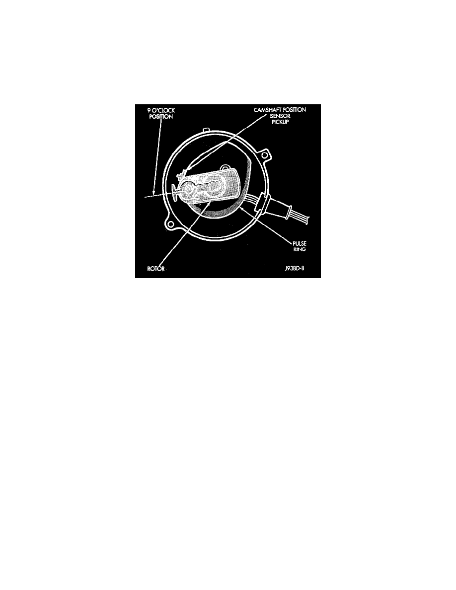
3. Set the voltmeter on a 15 Volt DIC scale. Remove distributor cap. Rotate engine (with starter) until pulse ring enters the magnetic pickup on
camshaft position sensor (distributor rotor should be pointed in 9 o'clock position). Turn ignition key to ON position. Voltmeter should read
approximately 5.0 volts.
If voltage is not present, check the voltmeter leads for a good connection.
4. If voltage is still not present, check for voltage at the supply wire. For wire identification, refer to Wiring Diagrams. See: Diagrams/Electrical
Diagrams
If voltage is not present at supply wire, remove the Powertrain Control Module (PCM) 60-way connector. Check for voltage at pin 7 and ground
with harness connected.
If voltage is still not present, perform vehicle test using the DRB II diagnostic scan tool.
If voltage is present at the supply wire, replace the camshaft position sensor.
5. If voltage is present at pin 7 but not at the supply wire:
a. Check continuity between the supply wire. Check between the distributor connector and pin 7 at the PCM. If continuity is not present, repair
the harness as necessary.
b. Check for continuity between the camshaft position sensor output wire and pin 44 at the PCM. If continuity is not present, repair the harness as
necessary.
c. Check for continuity between the ground circuit wire at the distributor connector and ground. If continuity is not present, repair the harness as
necessary.
6. While observing the voltmeter, crank the engine. The voltmeter needle should fluctuate between 0 and 5 volts while the engine is cranking. This
verifies that the camshaft position sensor in the distributor is operating properly and a sync pulse signal is being generated.
If sync pulse signal is not present, replacement of the camshaft position sensor is necessary. Refer to Camshaft Position Sensor removal and
installation in the Component Removal/installation Procedures section of this group. See: Service and Repair