
Grand Cherokee 4WD V8-4.7L (2003)
Power Mirror Switch: Description and Operation
POWER MIRROR SWITCH
Both the right and left power outside mirrors are controlled by a single multi-function switch unit located on the driver side front door trim panel.
The power mirror switch unit includes a three-position rocker selector switch and four momentary directional push button switches.
The power mirror switch unit is integral to the Driver Door Module (DDM). The power mirror switch cannot be repaired or adjusted and, if faulty
or damaged, the entire DDM unit must be replaced. (Refer to ELECTRICAL/ELECTRONIC CONTROL MODULES/DRIVER DOOR
MODULE - REMOVAL) for the DDM service procedures.
The power mirror selector switch is moved right (right mirror control), left (left mirror control), or center to turn the power outside mirror system
OFF. When the selector switch is in the right mirror control or left mirror control position, one of the four directional control buttons is depressed
to control movement of the selected mirror up, down, right, or left. When the selector switch is in the OFF position, depressing any of the
directional switches will not change either mirror position.
See the owner's manual in the vehicle glove box for more information on the features use and operation of the power mirror switches.
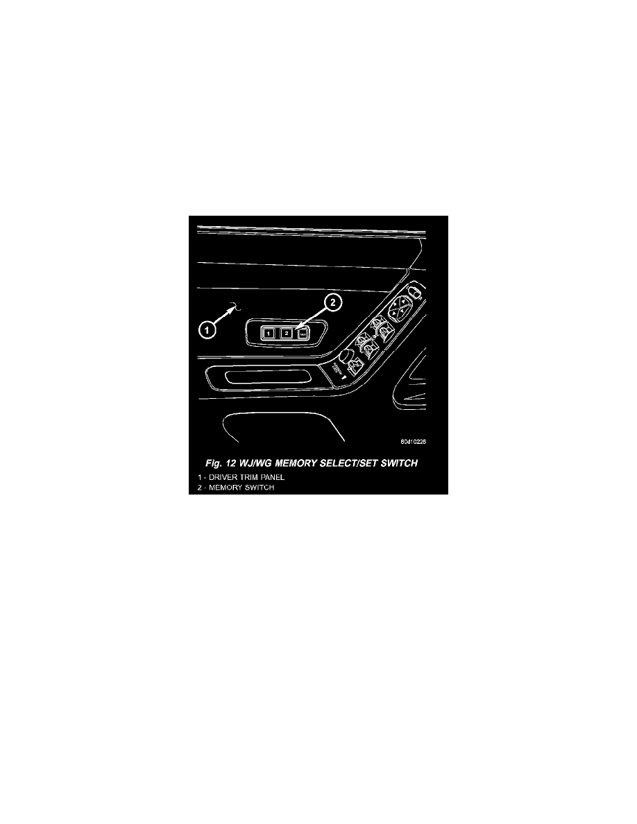
Fig.12 WJ/WG Memory Select/Set Switch
MEMORY SET SWITCH
Vehicles equipped with the memory system have a memory switch mounted to the driver side front door trim panel. This switch is used to set and
recall all of the memory system settings for up to two drivers. The memory switch is a resistor multiplexed unit that is hard wired to the Driver
Door Module (DDM), which is also located on the driver side front door trim panel. The DDM sends out the memory system set and recall
requests to the other electronic modules over the Programmable Communications Interface (PCI) data bus.
The memory switch cannot be adjusted or repaired and, if faulty or damaged, it must be replaced. For complete circuit diagrams, refer to Wiring
Diagrams.
The memory switch has three momentary switch buttons labeled Set, 1 and 2. The Driver 1 and Driver 2 buttons are back-lit with Light-Emitting
Diodes (LED) for visibility, and are also color-coded to coincide with the color-coded Driver 1 and Driver 2 Remote Keyless Entry (RKE)
transmitters. The Driver 1 memory switch button and RKE transmitter are black, and the Driver 2 memory switch button and RKE transmitter are
gray. The memory switch Set button also has an LED that will illuminate and flash to indicate that the memory system is in the set mode. This
LED will automatically be extinguished when a set request has been successfully completed.
See the owner's manual in the vehicle glove box for more information on the features, use and operation of the memory switch. For diagnosis of
the memory switch, the DDM or the PCI data bus, the use of a DRB scan tool and the proper Diagnostic Procedures are recommended.