
Grand Cherokee 4WD V8-4.7L (2003)
There are 5 individual delay times with a minimum delay of 1/2 second to a maximum of 18 seconds. When the vehicle speed is under 10 MPH (16
kmh), the delay time is doubled providing a range of 1 second to 36 seconds.
Mist Wipe
The wiper operates as long as the wiper switch is in the mist position.
Park After Ignition Off
Because the wiper relays are powered from the battery the BCM can run the wipers to park after the ignition is turned off.
Wipe After Wash
When the driver presses the wash button and then releases it, the wiper will continue to run for 3 additional wipe cycles.
The wiper system utilizes the BCM to control the on/off relay for low wiper functions, intermittent wiper delay as the switch position changes, wipe
after wash mode, and wiper motor park functions. The BCM uses the vehicle speed input to double the usual delay time below 10 MPH (16 kmh).
FRONT/REAR WIPER AND WASHER SWITCHES (RIGHT MULTI-FUNCTION SWITCH STALK)
The front windshield and rear liftglass wiper/ washer switches are located on the wiper multi- function switch stalk which is secured to the right side of
the multi-function switch mounting housing on the steering column.
A knob on the end of the wiper multifunction switch stalk is rotated to select the desired front wiper speed (HIGH or LOW) or one of the five
intermittent front wiper positions. The wiper stalk is pulled toward the driver to activate the windshield washer system. Both the front wiper and front
washer motors will operate continuously for as long as the stalk is held in the momentary FRONT WASH position.
Another rotary switch on the wiper multi-function switch stalk is rotated to select the desired rear wiper speed (ON or DELAY). The wiper stalk is
pushed toward the instrument panel to activate the rear liftglass washer system. Both the rear wiper and rear washer motors will operate continuously
for as long as the stalk is held in the momentary REAR WASH position.
If any part of the right multi-function switch stalk is faulty or damaged, the entire wiper multi-function switch assembly must be replaced.
REAR WIPER SYSTEM
Five circuits feed the rear wiper module. It has two high current circuits, battery (B+) and ground, that run the motor. The remaining three circuits are
low current control circuits.
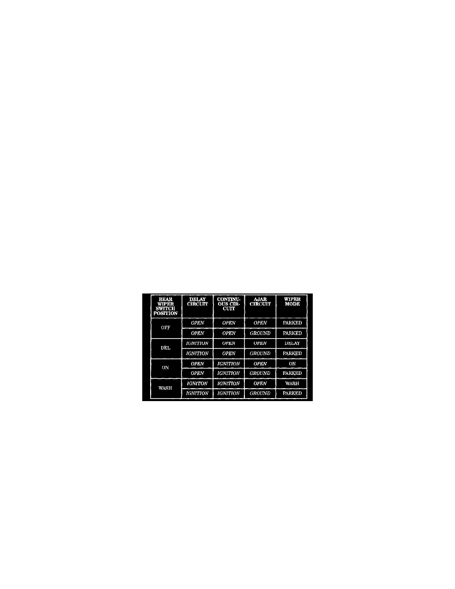
Rear Wiper System Control Circuit
Two of these circuits come from the rear wiper switch on the right multi-function switch stalk. These circuits are referred to as the rear wiper motor
control circuit and the rear wiper motor intermittent control circuit. When the rear wiper switch is in the Off position, both of these circuits are open
and the wiper module parks or remains parked. When the rear wiper switch is in the Intermittent position, the intermittent control circuit is switched to
ignition voltage, the motor control circuit is open and the wiper is in the intermittent modes. When the rear wiper switch is in the On position, the
intermittent control circuit is open and the motor control circuit is switched to ignition voltage and the wiper is in continuous wipe mode.
The third control circuit is the AJAR circuit. This circuit is fed by the flip-up glass ajar switch. When the flip-up glass is closed the ajar switch is open
and the rear wiper module functions normally. When the flip-up glass is open, the ajar switch is closed and the circuit provides ground to the module.
This ground signal indicates to the rear wiper module that it should park if operating or not allow operation if parked.