
Grand Cherokee 4WD V8-4.7L (2003)
Air Bag Control Module: Description and Operation
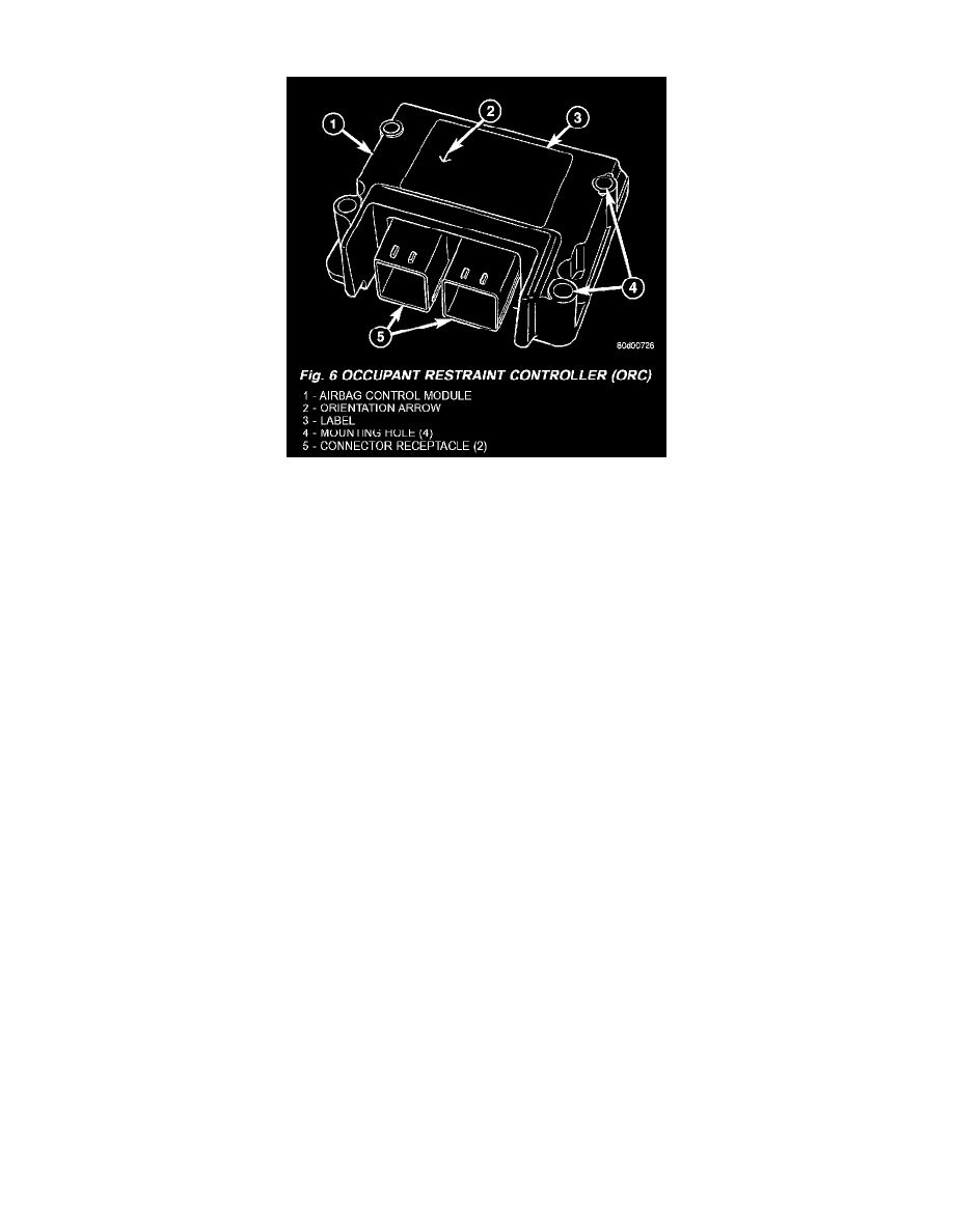
Fig. 6 Occupant Restraint Controller (ORC)
AIRBAG CONTROL MODULE (ACM)
The Airbag Control Module (ACM) is also sometimes referred to as the Occupant Restraint Controller (ORC). The ACM is concealed beneath the
center floor console, where it is secured by four screws to a stamped steel mounting bracket welded onto the top of the floor panel transmission tunnel
just forward of the park brake mechanism in the passenger compartment of the vehicle. Concealed within a hollow in the center of the die cast
aluminum ACM housing is the electronic circuitry of the ACM which includes a microprocessor, an electronic impact sensor, an electronic safing
sensor, and an energy storage capacitor. A stamped metal cover plate is secured to the bottom of the ACM housing with four screws to enclose and
protect the internal electronic circuitry and components.
An arrow printed on the label on the top of the ACM housing provides a visual verification of the proper orientation of the unit, and should always be
pointed toward the front of the vehicle. Two molded plastic electrical connector receptacles exit the forward side of the ACM housing. These two
receptacles connect the ACM to the vehicle electrical system through a dedicated take out and connector of the instrument panel wire harness, and a
dedicated take out and connector of the airbag overlay wire harness. For vehicles equipped with the optional side curtain airbags, both ACM connector
receptacles are black in color and the ACM contains a second bi-directional safing sensor for the side airbags. For vehicles not equipped with the
optional side curtain airbags, the ACM connector receptacles are both gray.
The impact sensor and safing sensor internal to the ACM are calibrated for the specific vehicle, and are only serviced as a unit with the ACM. The
ACM cannot be repaired or adjusted and, if damaged or faulty it must be replaced.
The microprocessor in the Airbag Control Module (ACM) contains the supplemental restraint system logic circuits and controls all of the
supplemental restraint system components. The ACM uses On-Board Diagnostics (OBD) and can communicate with other electronic modules in the
vehicle as well as with the DRBIII scan tool using the Programmable Communications Interface (PCI) data bus network. This method of
communication is used for control of the airbag indicator in the ElectroMechanical Instrument Cluster (EMIC) and for supplemental restraint system
diagnosis and testing through the 16-way data link connector located on the driver side lower edge of the instrument panel.
The ACM microprocessor continuously monitors all of the supplemental restraint system electrical circuits to determine the system readiness. If the
ACM detects a monitored system fault, it sets an active and stored Diagnostic Trouble Code (DTC) and sends electronic messages to the EMIC over
the PCI data bus to turn on the airbag indicator. An active fault only remains for the duration of the fault or in some cases the duration of the current
ignition switch cycle, while a stored fault causes a DTC to be stored in memory by the ACM. For some DTCs, if a fault does not recur for a number of
ignition cycles, the ACM will automatically erase the stored DTC. For other internal faults, the stored DTC is latched forever.
The ACM also monitors a Hall effect-type seat belt switch located in the buckle of the driver side front seat belt to determine whether the seatbelt is
buckled, and provides an input to the EMIC over the PCI data bus to control the seatbelt indicator operation based upon the status of the driver side
front seat belt switch.
The ACM receives battery current through two circuits; a fused ignition switch output (run) circuit through a fuse in the Junction Block (JB), and a
fused ignition switch output (start-run) circuit through a second fuse in the JB. The ACM is grounded through a ground circuit and take out of the
instrument panel floor wire harness. This take out has a single eyelet terminal connector secured by a nut to a ground stud located behind the ACM
mount on the floor panel transmission tunnel. These connections allow the ACM to be operational whenever the ignition switch is in the Start or On
positions.