
Grand Cherokee 4WD V8-4.7L VIN N (2000)
Remote Switch: Description and Operation
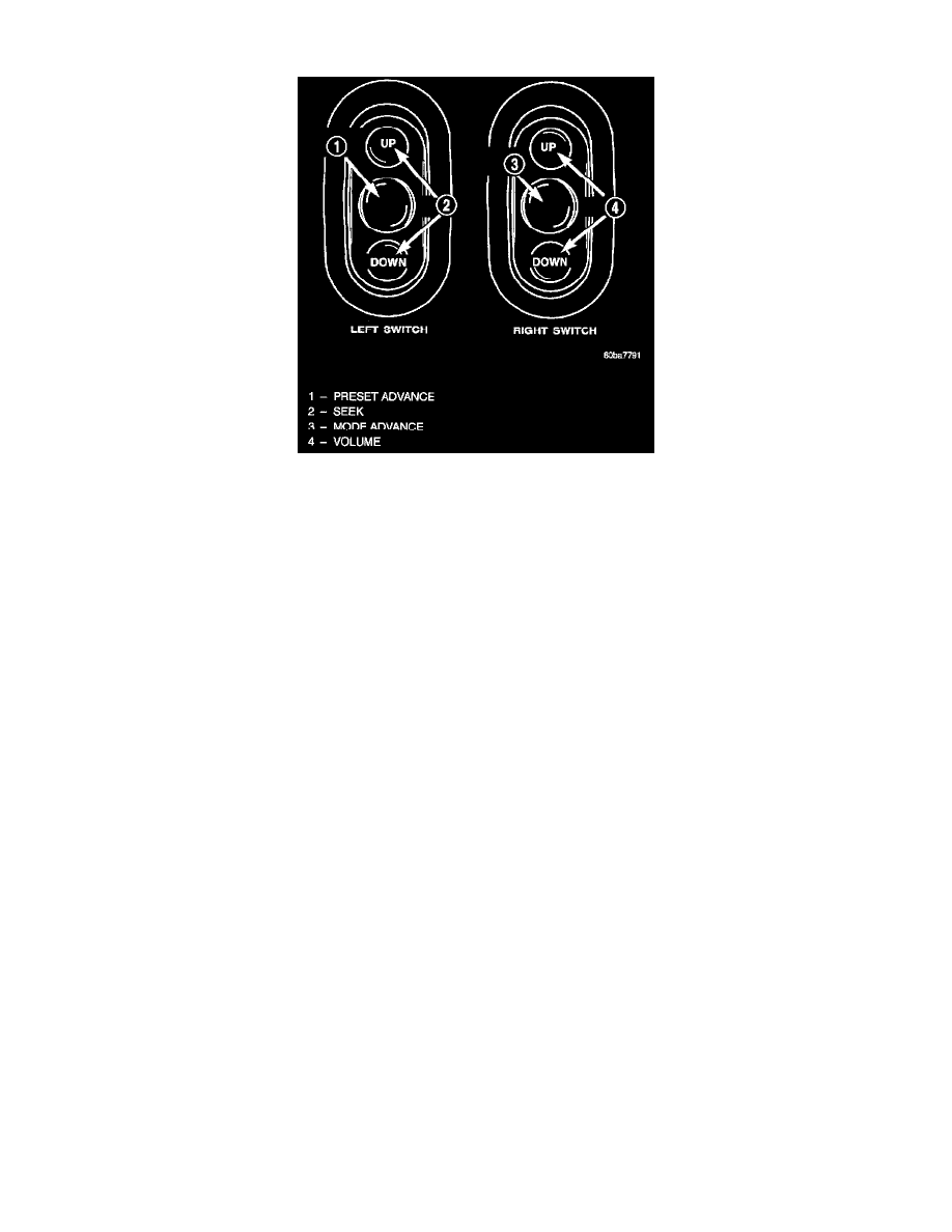
Remote Radio Switches
Remote radio control switches are included on models equipped with the optional leather-wrapped steering wheel. The two rocker-type switch units are
mounted in the upper spoke covers of the rear (instrument panel side) steering wheel trim cover. The switch unit on the left side is the seek switch and
has seek up, seek down, and preset station advance switch functions. The switch unit on the right side is the volume control switch and has volume up,
volume down, and mode advance switch functions.
The two remote radio switch units are each retained in a mounting hole located on opposite sides of the rear steering wheel trim cover by four integral
snap features. A plastic bracket on the back of each switch unit provides additional support for the unit by extending towards the center of the steering
wheel where it is clamped between the steering wheel armature and the steering wheel rear trim cover mounting boss by the trim cover mounting screw.
The two remote radio switch units share a common steering wheel wire harness with the vehicle speed control switches. The steering wheel wire harness
is connected to the instrument panel wire harness through the clockspring.
The six switches in the two remote radio switch units are normally open, resistor multiplexed momentary switches that are hard wired to the Body
Control Module (BCM) through the clockspring. The BCM sends a five volt reference signal to both switch units on one circuit, and senses the status of
all of the switches by reading the voltage drop on a second circuit.
When the BCM senses an input (voltage drop) from any one of the remote radio switches, it sends the proper switch status messages on the
Programmable Communication Interface (PCI) data bus network to the radio receiver. The electronic circuitry within the radio receiver is programmed
to respond to these remote radio switch status messages by adjusting the radio settings as requested. For diagnosis of the BCM or the PCI data bus, the
use of a DRB scan tool and the proper Diagnostic Procedures are recommended.
For more information on the features and control functions for each of the remote radio switches, see the owner's manual in the vehicle glove box.