
Grand Cherokee 4WD V8-4.7L VIN N (2000)
Terminal Removal Using Special Tool
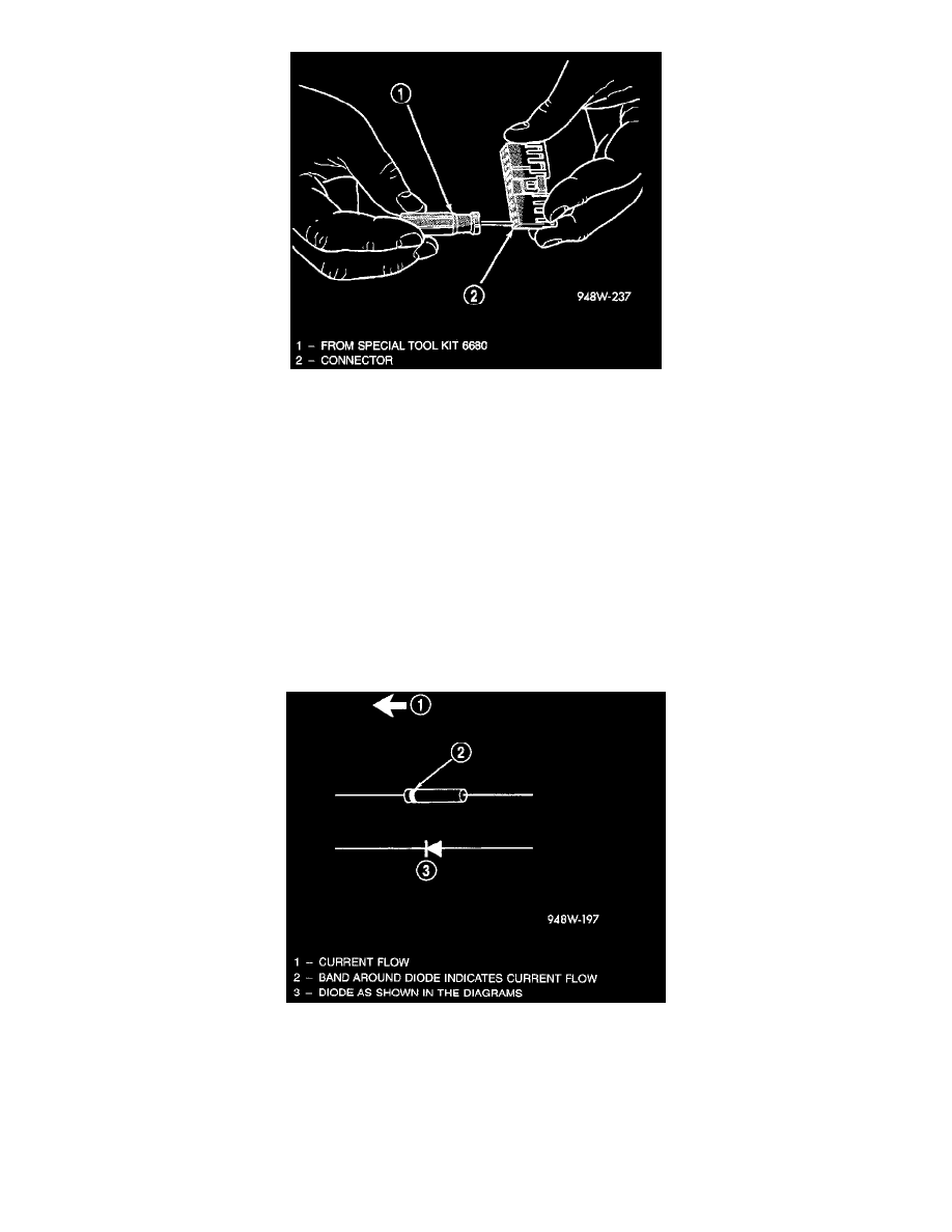
4. Position the connector locking finger away from the terminal using the proper pick from special tool kit 6680. Pull on the wire to remove the
terminal from the connector.
5. Reset the terminal locking tang, if it has one.
6. Insert the removed wire in the same cavity on the repair connector.
7. Repeat steps four through six for each wire in the connector, being sure that all wires are inserted into the proper cavities. For additional connector
pinout identification, refer to the wiring diagrams.
8. Insert the connector locking wedge into the repaired connector, if required.
9. Connect connector to its mating half/component.
10. Connect battery and test all affected systems.
Diode Replacement
REMOVAL
1. Disconnect the battery.
2. Locate the diode in the harness, and remove the protective covering.
Diode Identification
3. Remove the diode from the harness, pay attention to the current flow direction.
INSTALLATION
1. Remove the insulation from the wires in the harness. Only remove enough insulation to solder in the new diode.
2. Install the new diode in the harness, making sure current flow is correct. If necessary, refer to the appropriate wiring diagram for current flow (Fig.
13).
3. Solder the connection together using rosin core type solder only Do not use acid core solder.