
Grand Cherokee 4WD V8-5.2L VIN Y (1998)
Hydraulic Control Assembly - Antilock Brakes: Description and Operation
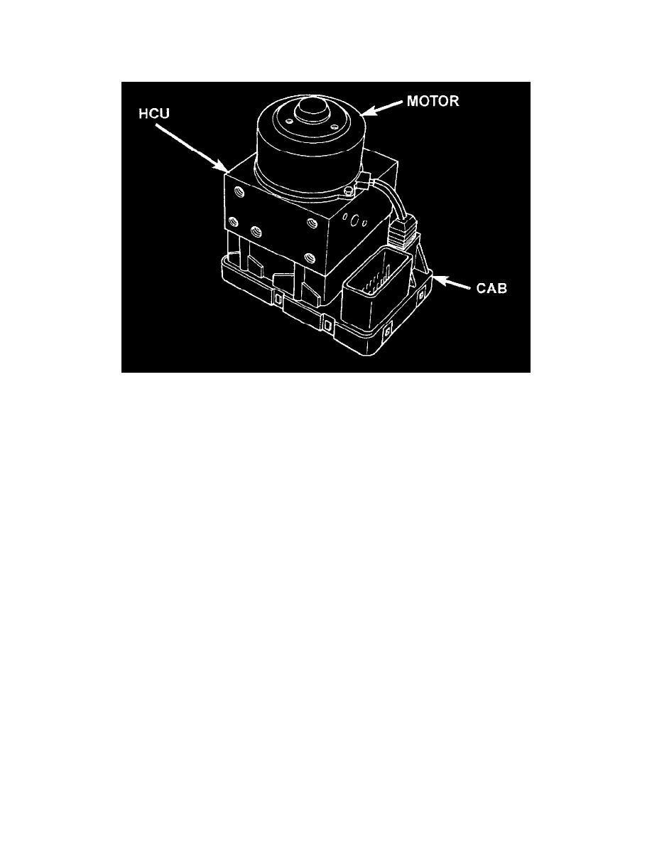
Hydraulic Control Unit (HCU)
HYDRAULIC CONTROL UNIT
Controller Antilock Brakes (CAB)
The Hydraulic Control Unit (HCU) contains the valve block assembly, four accumulators, the pump/motor assembly and wire harnesses.
The pump, motor, and accumulators are combined into an assembly and is attached to the valve body. The accumulators store the extra fluid
released to the system for ABS mode operation. The pump provides the fluid volume needed and is operated by a DC type motor. The motor is
controlled by the CAB.
Valve Block Assembly
The valve block assembly contains 6 valves with three inlet valves and three outlet valves. The inlet valves are spring-loaded in the open position
and the outlet valves are spring loaded in he closed position. During an anti lock stop, these valves are cycled to maintain the proper slip ration for
each channel. If a wheel locks, the inlet valve is closed to prevent any further pressure increase. Then the outlet valve is opened to release the
pressure to the accumulators until the wheel is no longer slipping. Once the wheel is no longer slipping, the outlet valve is closed and the inlet
valve is opened to reapply pressure. If the wheel is decelerating within its predetermined limits (proper slip ratio), both valves will close to hold
the pressure constant.
Pump/Motor Assembly
The pump/motor assembly provides the extra amount of fluid needed during antilock braking. The pump is supplied fluid that is released to the
accumulators when the outlet valve is opened during an antilock stop. The pump is also used to drain the accumulator circuits after the anti lock
stop is complete. The pump is operated by an integral electric motor. This DC-type motor is controlled by the CAB. The CAB turns on the motor
when an antilock stop is detected. The pump continues to run during the antilock stop and is turned oft approximately 3-5 seconds after the stop is
complete. The pump mechanism consists of two opposing pistons operated by an eccentric cam. One piston supplies the primary hydraulic circuit.
The opposing piston supplies the secondary hydraulic circuit. In operation, one piston draws fluid from the accumulators. The opposing piston
pumps fluid to the valve body solenoids. The CAB monitors the pump/motor operation internally.
Accumulators
The accumulators provide temporary fluid storage during an anti lock stop and are drained by the pump/motor. The 6mm (0.24") accumulator is
used for the front brakes, the 3mm (0.12") accumulator is used for the rear brakes, the 1 mm (0.04") accumulator is used for the lip seal saver, and
the 0.5mm (0.02") accumulator is used for noise reduction.
The HCU provides three channel pressure control to the front and rear brakes. One channel controls the rear wheel brakes in tandem. The two
remaining channels control the front wheel brakes individually.
During antilock braking, the solenoid valves are opened and closed as needed. The valves are not static. They are cycled rapidly and continuously
to modulate pressure and control wheel slip and deceleration.