
Grand Cherokee 4WD V8-5.2L VIN Y (1998)
Wiper Relay: Testing and Inspection
WARNING: ON VEHICLES EQUIPPED WITH AIR-BAGS, REFER TO AIRBAGS SYSTEMS BEFORE ATTEMPTING ANY STEERING
WHEEL, STEERING COLUMN, OR INSTRUMENT PANEL COMPONENT DIAGNOSIS OR SERVICE. FAILURE TO TAKE THE
PROPER PRECAUTIONS COULD RESULT IN ACCIDENTAL AIR-BAG DEPLOYMENT AND POSSIBLE PERSONAL INJURY.
Relay Test
Intermittent Wipe Relay
The intermittent wipe relay is located in the Power Distribution Center (PDC) in the engine compartment. Refer to the PDC label for intermittent wipe
relay identification and location.
Remove the intermittent wipe relay from the PDC as described to perform the following tests:
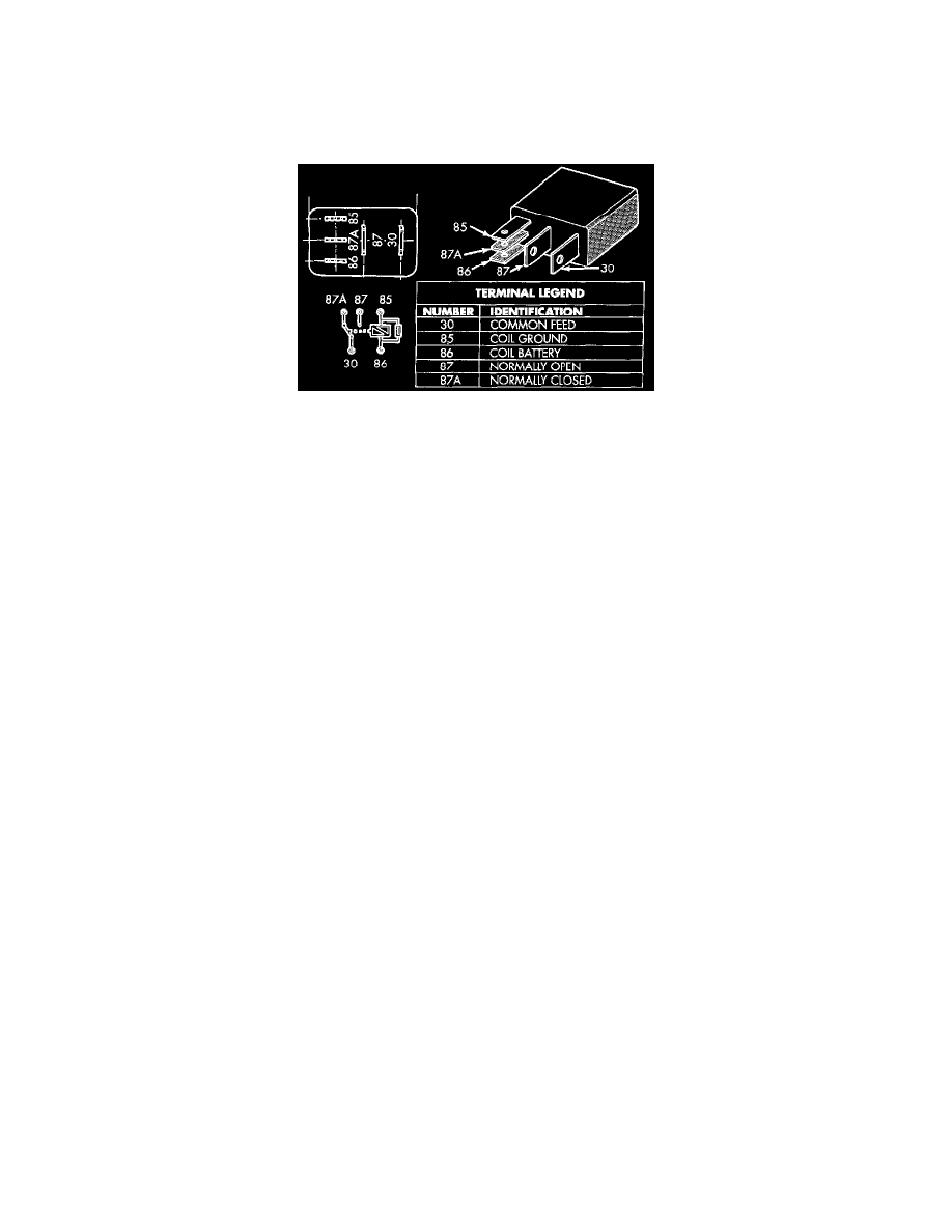
1. A relay in the de-energized position should have continuity between terminals 87A and 30, and no continuity between terminals 87 and 30. If OK,
go to Step 2. If not OK, replace the faulty relay.
2. Resistance between terminals 85 and 86 (electromagnet) should be 75 ± 5 Ohms. If OK, go to Step 3. If not OK, replace the faulty relay.
3. Connect a battery to terminals 85 and 86. There should now be continuity between terminals 30 and 87, and no continuity between terminals 87A
and 30. If OK, see the Relay Circuit Test. If not OK, replace the faulty relay.
Relay Circuit Test
1. the relay common feed terminal cavity (30) is connected to the wiper (multi-function) switch. There should be continuity between the cavity for
relay terminal 30 and the two fused ignition switch output (V6) circuit cavities of the multi-function switch connector at all times. If OK, go to
Step 2. If not OK, repair the open circuit(s) to the multi-function switch as required.
2. The relay normally closed terminal (87A) is connected to terminal 30 in the de-energized position. There should be continuity between the cavity
for relay terminal 87A and the wiper park switch sense circuit cavities of the wiper motor wire harness connector and the white 24-way Body
Control Module (BCM) wire harness connector at all times. If OK, go to Step 3. If not OK, repair the open circuit(s) to the wiper motor and BCM
as required.
3. The relay normally open terminal (87) is connected to the common feed terminal (30) in the energized position. There should be battery voltage at
the cavity for relay terminal 87 with the ignition switch in the On or Accessory positions. If OK, go to Step 4. If not OK, repair the open circuit to
the ignition switch as required.
4. The coil battery terminal (86) is connected to the electromagnet in the relay. There should be battery voltage at the cavity for relay terminal 86
with the ignition switch in the On or Accessory positions. If OK, go to Step 5. If not OK, repair the open circuit to the ignition switch as required.
5. The coil ground terminal (85) is connected to the electromagnet in the relay. It is grounded by the BCM to energize the relay and cycle the wiper
motor. Check for continuity between the cavity for relay terminal 85 and the intermittent wiper relay control circuit cavity of the white 24-way
BCM wire harness connector. There should be continuity. If OK, refer to the proper Diagnostic Procedures for diagnosis of the BCM. If not OK,
repair the open circuit to the BCM as required.