
Grand Cherokee 4WD V8-5.2L VIN Y (1998)
Four-Wheel Drive (4WD) Switch: Component Tests and General Diagnostics
Four-Wheel Drive Display And Indicators/Service 4WD Switch
If the problem being diagnosed is related to an incorrect or no four-wheel drive display or indicator functions, be certain to confirm that the problem is
with the VIC module and transfer case switch circuits, and not with a Powertrain Control Module (PCM) with an incorrect Vehicle Identification
Number (VIN). This condition can only occur if the original PCM was replaced with a unit from another vehicle. The VIC module uses the VIN
message received on the CCD data bus from the PCM to determine if the vehicle is equipped with two-wheel drive or four-wheel drive.
If a four-wheel drive vehicle has a two-wheel drive VIN entered in the PCM, the VIC will ignore all transfer case switch inputs. If a two-wheel drive
vehicle has a four-wheel drive VIN entered in the PCM, the rear wheels in the VIC display will not light. Use a DRB scan tool and the proper
Powertrain Management/Computers and Control Systems/Testing and Inspection/Diagnostic Charts Procedures to confirm the VIN in the PCM.
In addition, it should be noted that a VIC "Service 4WD Switch" message on a two-wheel drive vehicle can occur if a short circuit occurs in the
transfer case switch circuits from the VIC module, in combination with a PCM having a four-wheel drive VIN. To locate the short circuit, start at Step
3 of the following diagnostic procedure. Two-wheel drive models do have the same VIC wire harness provisions as four-wheel drive models.
WARNING: ON VEHICLES EQUIPPED WITH AIRBAGS, REFER TO AIR BAGS AND SEAT BELTS/AIR BAGS BEFORE
ATTEMPTING STEERING WHEEL, STEERING COLUMN, OR INSTRUMENT PANEL COMPONENT DIAGNOSIS OR SERVICE.
FAILURE TO TAKE THE PROPER PRECAUTIONS COULD RESULT IN ACCIDENTAL AIR-BAG DEPLOYMENT AND POSSIBLE
PERSONAL INJURY.
1. Unplug the wire harness connector at the transfer case switch. Check for continuity between the ground circuit cavity of the transfer case switch
wire harness connector and a good ground. There should be continuity if OK, go to Step 2. if not OK, repair the open circuit as required.
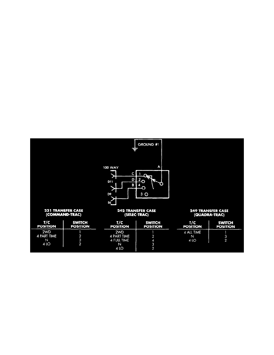
Transfer Case Switch
2. Check the transfer case switch continuity while shifting the transfer case shift lever to the proper positions. The switch continuity should be as
shown. If OK, go to Step 3. If not OK, replace the faulty switch.
3. Disconnect and isolate the battery negative cable. Remove the VIC module as described. Unplug the VIC module wire harness connector.
4. Locate two pairs of wire harness connectors located in the wire harness leading to the VIC module. The wire harness connectors should be taped
back to the harness. One pair of connectors are black with a single cavity. The other pair are red with two cavities. If the vehicle has the
Quadra-Trac 4WD transfer case, only the red wire harness connectors should be joined. If the vehicle has the Command-Trac or Selec-Trac 4WD
transfer case, only the black wire harness connectors should be joined. In all cases, only one pair of wire harness connectors should be joined. If
OK, go to Step 5. If not OK, correct the wire harness connections as required.