
Grand Cherokee 4WD V8-5.2L VIN Y (1998)
Heated Glass Element Relay: Testing and Inspection
WARNING: ON VEHICLES EQUIPPED WITH AIR-BAGS, REFER TO AIRBAGS SYSTEMS BEFORE ATTEMPTING ANY STEERING
WHEEL, STEERING COLUMN, OR INSTRUMENT PANEL COMPONENT DIAGNOSIS OR SERVICE. FAILURE TO TAKE THE
PROPER PRECAUTIONS COULD RESULT IN ACCIDENTAL AIR-BAG DEPLOYMENT AND POSSIBLE PERSONAL INJURY.
Relay Test
Defogger Relay
The defogger relay is located in the junction block, on the right cowl side inner panel below the instrument panel in the passenger compartment.
Remove the defogger relay from the junction block to perform the following tests:
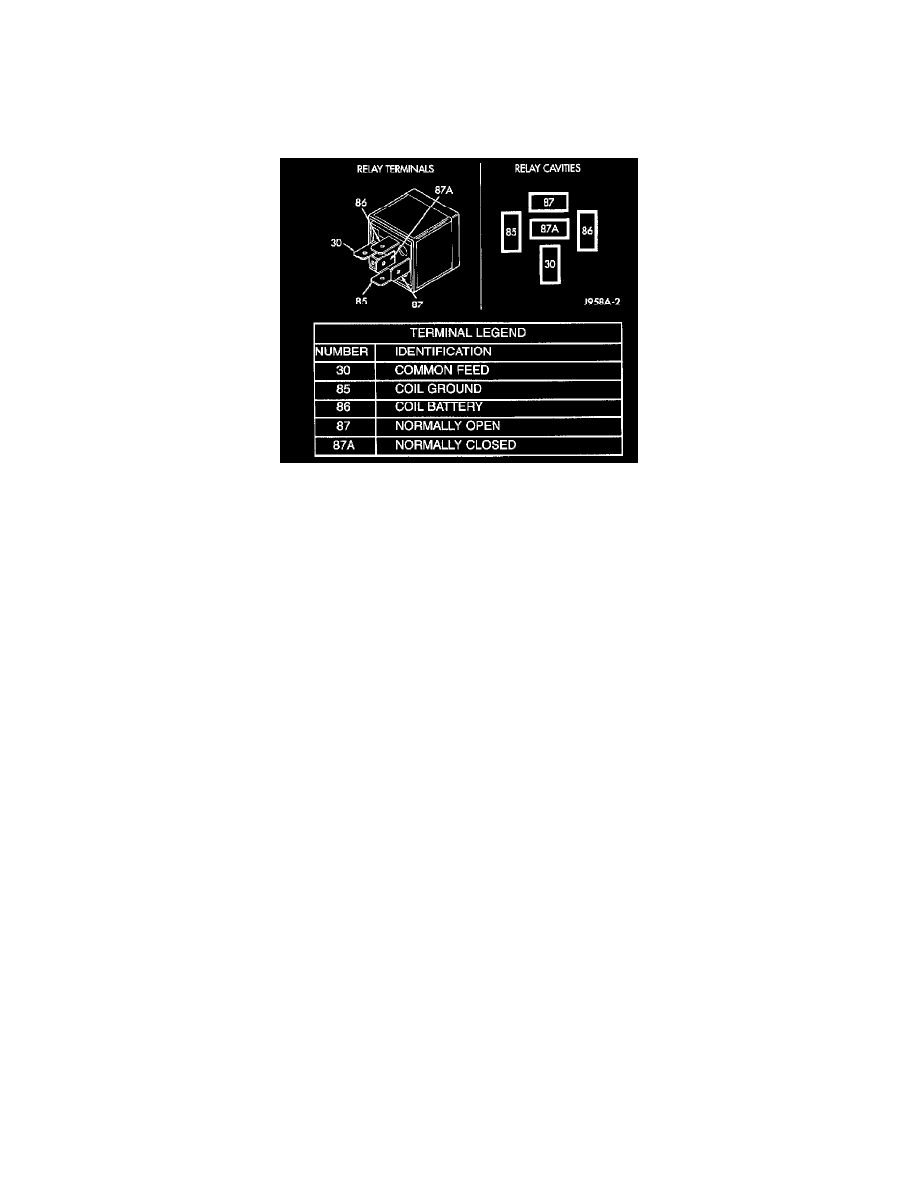
1. A relay in the de-energized position should have continuity between terminals 87A and 30, and no continuity between terminals 87 and 30. If OK,
go to Step 2. If not OK, replace the faulty relay.
2. Resistance between terminals 85 and 86 (electromagnet) should be 75 ± 10 Ohms. If OK, go to Step 3. If not OK, replace the faulty relay
3. Connect a battery to terminals 85 and 86. There should now be continuity between terminals 30 and 87, and no continuity between terminals 87A
and 30. If OK, see the Relay Circuit Test. If not OK, replace the faulty relay.
Relay Circuit Test
1. The relay common feed terminal cavity (30) is connected to battery voltage and should be hot at all times. If OK, go to Step 2. If not OK, repair
the open circuit to the PDC fuse as required.
2. The relay normally closed terminal (87A) is connected to terminal 30 in the de-energized position, but is not used for this application. Go to Step
3.
3. The relay normally open terminal (87) is connected to the common feed terminal (30) in the energized position. This terminal supplies battery
voltage to the fuse in the junction block that feeds the rear glass heating grid and the defogger switch LED indicator. There should be continuity
between the cavity for relay terminal 87 and the rear glass heating grid and defogger switch LED indicator at all times. If OK, go to Step 4. If not
OK, repair the open circuit as required.
4. The coil battery terminal (86) is connected to the electromagnet in the relay. It is connected to battery voltage and should be hot at all times. Check
for battery voltage at the cavity for relay terminal 86. If OK, go to Step 5. If not OK, repair the open circuit to the PDC fuse as required.
5. The coil ground terminal (85) is connected to the electromagnet in the relay. This terminal is provided with ground by the Body Control Module
(BCM) rear window defogger timer and logic circuitry to energize the defogger relay. There should be continuity to the rear window defogger
relay control circuit cavity of the white 24-way BCM wire harness connector. If OK, use a DRB scan tool and the proper Diagnostic Procedures to
test the BCM. If not OK, repair the open circuit as required.