
Grand Cherokee 4WD Laredo V8-4.7L (2002)
Refrigerant: Service and Repair
Refrigerant - Charge
WARNING: REVIEW THE WARNINGS AND CAUTIONS IN THE FRONT OF THIS SECTION BEFORE PERFORMING THE
FOLLOWING OPERATION.
After the refrigerant system has been tested for leaks and evacuated, a refrigerant charge can be injected into the system.
A R-134a refrigerant recovery/recycling/charging station that meets SAE Standard J2210 must be used to charge the refrigerant system with R-134a
refrigerant. Refer to the operating instructions supplied by the equipment manufacturer for proper care and use of this equipment.
Partial Charge Method
WARNING: REVIEW THE WARNINGS AND CAUTIONS IN THE FRONT OF THIS SECTION BEFORE PERFORMING THE
FOLLOWING OPERATION.
The partial charge method is used to add a partial charge to a refrigerant system that is low on refrigerant. To perform this procedure the evaporator
inlet and outlet tube temperatures are measured. The temperature difference is measured with a temperature meter with one or two clamp-on
thermocouple probes. The difference between the evaporator inlet and outlet tube temperatures will determine the amount of refrigerant needed.
Before adding a partial refrigerant charge, check for refrigerant system leaks.
If a leak is found, make the necessary repairs before attempting a full or partial refrigerant charge.
1. Attach a manifold gauge set to the refrigerant system service ports.
2. Attach the two clamp-on thermocouple probes to the inlet and outlet tubes of the evaporator coil.
-
If a single thermocouple probe is used, attach the probe to the evaporator inlet tube just before the collar of the refrigerant line connector
fitting. The probe must make contact with the bottom surface of the evaporator inlet tube.
-
If dual thermocouple probes are used, attach probe 1 to the evaporator inlet tube, and probe 2 to the evaporator outlet tube. Attach both probes
to the evaporator tubes just before the collar of the refrigerant line connector fittings. The probes must make contact with the bottom surfaces
of the evaporator inlet and outlet tubes.
3. Open all of the windows or doors of the passenger compartment.
4. Set the A/C button on the A/C Heater controls to the ON position, the temperature control knob in the full cool position, select Recirculation
Mode, and place the blower motor switch in the highest speed position.
5. Start the engine and hold the engine idle speed at 1,000 rpm. Allow the engine to warm up to normal operating temperature.
6. The compressor clutch may cycle, depending upon ambient temperature, humidity and the refrigerant system charge level.
7. Hold the engine idle speed at 1,000 rpm.
8. Allow three to five minutes for the refrigerant system to stabilize, then record the temperatures of the evaporator inlet and outlet tubes.
-
If a single probe is used, record the temperature of the evaporator inlet tube. Then remove the probe from the inlet tube and attach it to the
evaporator outlet tube just before the collar of the refrigerant line connector fitting. The probe must make contact with the bottom surface of
the evaporator outlet tube. Allow the thermocouple and meter time to stabilize, then record the temperature of the evaporator outlet tube.
Subtract the inlet tube temperature reading from the outlet tube temperature reading.
-
If dual probes are used, record the temperatures of both the evaporator inlet and outlet tubes. Then subtract the inlet tube temperature reading
from the outlet tube temperature reading.
9. If the measured temperature differential is higher than 22 °C to 26 °C (40 °F to 47 °F), add 0.4 kilograms (14 ounces) of refrigerant.
10. Allow three to five minutes for the refrigerant system to stabilize, then take a second set of thermocouple measurements. Record the temperature
difference to determine if an additional charge is required.
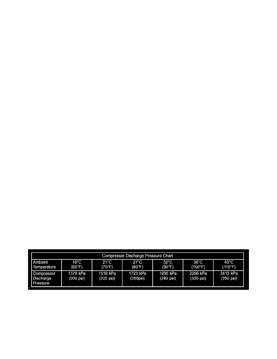
Compressor Discharge Pressure Chart
11. Record the compressor discharge pressure. If the reading is higher than the pressure shown in the Compressor Discharge Pressure Chart, the
system could be overcharged. If the reading is equal to, or lower, than the pressure shown in the chart, continue with this procedure.
12. EXAMPLE: The ambient temperature is 21 °C (70 °F). The evaporator inlet tube temperature is 12 °C (54 °F) and the evaporator outlet tube
temperature is 10 °C (50 °F). Subtract the inlet tube temperature from the outlet tube temperature. The difference is -2 °C (-4 °F). With a -21 °C
(-41 ° F) temperature differential at 21 °C (70 °F) ambient temperature, the system is fully charged.
13. Add enough refrigerant to bring the refrigerant system up to a full charge.
14. Remove the jumper wire from the low pressure cycling clutch switch wire harness connector and plug the connector back into the switch.