
Grand Cherokee 4WD Laredo V8-4.7L (2002)
receptacle shell that are used to secure the cigar lighter heating element to the insulated contact.
POWER OUTLET RELAY
The power outlet / cigar lighter relay is an electromechanical device that switches fused battery current to the cigar lighter or power outlet when
the ignition switch is turned to the Accessory or ON positions. The power outlet / cigar lighter relay is located in the junction block, below the
driver side of the instrument panel in the passenger compartment.
The cigar lighter relay is a International Standards Organization (ISO) relay Relays conforming to the ISO specifications have common physical
dimensions, current capacities, terminal patterns, and terminal functions.
The cigar lighter relay cannot be repaired or adjusted and, if faulty or damaged, it must be replaced.
The ISO relay consists of an electromagnetic coil, a resistor or diode, and three (two fixed and one movable) electrical contacts. The movable
(common feed) relay contact is held against one of the fixed contacts (normally closed) by spring pressure. When the electromagnetic coil is
energized, it draws the movable contact away from the normally closed fixed contact, and holds it against the other (normally open) fixed contact.
When the electromagnetic coil is de-energized, spring pressure returns the movable contact to the normally closed position. The resistor or diode is
connected in parallel with the electromagnetic coil in the relay, and helps to dissipate voltage spikes that are produced when the coil is
de-energized.
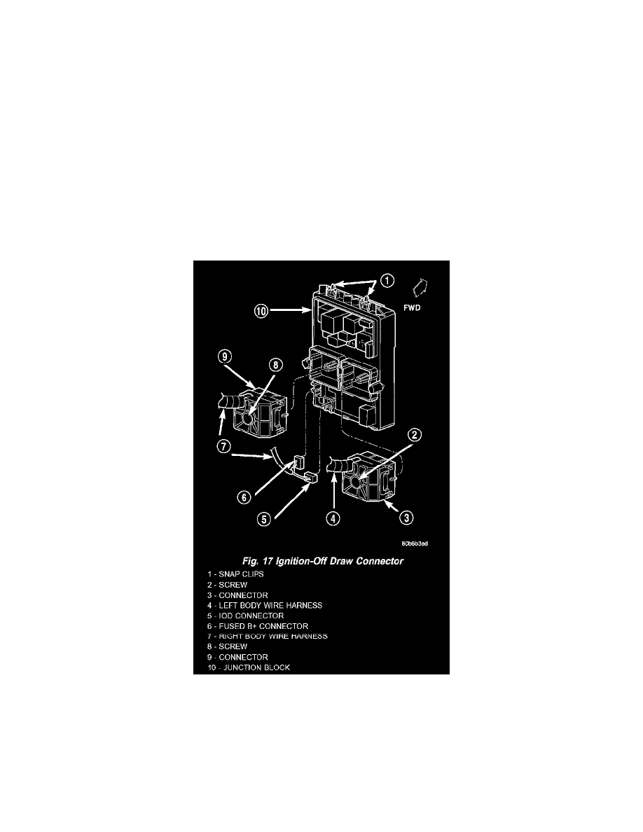
Fig.17 Ignition-Off Draw Connector
IOD WIRE HARNESS CONNECTOR
All vehicles are equipped with an Ignition-Off Draw (IOD) connector that is located in a molded connector receptacle on the lower rear surface of
the Junction Block (JB) housing (Fig. 17). The JB is concealed above the molded plastic instrument panel fuse cover. Integral latches molded into
the fuse cover secure it the JB, the Body Control Module (BCM) and the 16-way data link connector tab of the instrument panel steering column
support bracket. The fuse cover can be pulled downward to disengage the latches and provide service access to all of the fuses, relays and wire
harness connectors of the JB.
Refer to Instrument Panel Fuse Cover in the index for the location of additional service information covering the fuse cover.