
Grand Cherokee 4WD Laredo V8-4.7L (2002)
The bus messages are transmitted at a rate averaging 10800 bits per second. Since there is only voltage present when the modules transmit and the
message length is only about 500 milliseconds, it is ineffective to try and measure the bus activity with a conventional voltmeter. The preferred
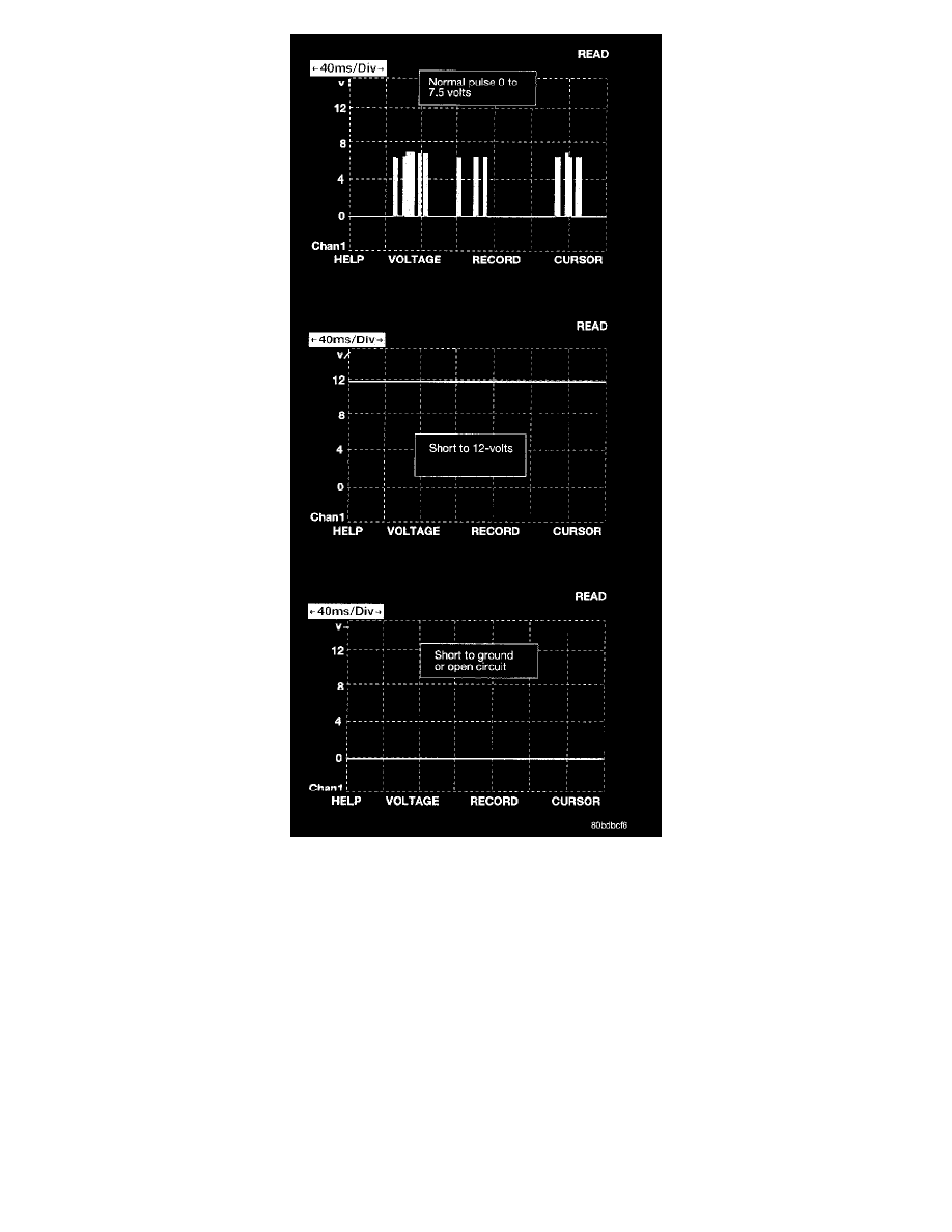
method is to use DRB III lab scope. The 12v square wave selection on the 20-volt scale provides a good view of the bus activity. Voltage on the
bus should pulse between zero and about seven and a half volts. Refer to the figure for some typical displays.
The PCI Bus failure modes are broken down into two categories. Complete PCI Bus Communication Failure and individual module no response.
Causes of complete PCI Bus Communication Failure include a short to ground or battery on the PCI circuit. Individual module no response can be
caused by an open circuit at either the Diagnostic Junction Port or the module, or an open battery or ground circuit to the affected module.
Symptoms of a complete PCI Bus Communication Failure would include but are not limited to:
-
All gauges on the EMIC stay at zero
-
All telltales on EMIC illuminate
-
EMIC backlighting at full intensity
-
Dashed lines in the EVIC ambient temperature display
-
No response received from any module on the PCI bus (expect the PCM/ECM)
-
No start (if equipped with Sentry Key Immobilizer)
Symptoms of Individual module failure could include any one or more of the above. The difference would be that at least one or more modules
would respond to the DRB III.