
Grand Wagoneer V8-360 5.9L VIN 7 2-bbl (1989)
2.
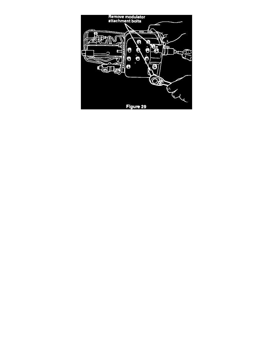
Remove two modulator-to-mounting bracket attachment bolts, located on the bottom of the hydraulic unit, (Figure 29).
3.
Unclip tubes from front of actuator.
4.
Remove the modulator & tube bundle by tilting the modulator forward and down. Avoid excessive bending of the tubes.
5.
Remove the two actuator mounting nuts.
6.
Remove the actuator from the mounting studs on the bracket. Disconnect the actuator-to-modulator boost line from the actuator and
install it to the new actuator. Tighten the fitting to 10 ft.lbs. (13.6 N-m). Also transfer the plastic tube clip to the new actuator.
7.
Install the new actuator over the mounting studs.
8.
Install the actuator mounting nuts and tighten them to 27 ft.lbs. (36.6 N-m).
9.
Install the modulator and tube bundle to the assembly. Avoid excessive bending of the tubes.
10.
Clip the tubes to the front of the actuator.
11.
Install the two modulator attachment bolts. Tighten them to 12 ft.lbs.
(16.3 N-m).
12.
Reconnect the four lines which were disconnected previously. Tighten the fittings to 10 ft.lbs. (13.6 N-m). Do Not over-tighten as the
casting threads may strip.
Hydraulic Unit Installation
J.
Hydraulic Unit Installation
1.
Install the brake light switch on the push rod end and insert the bushings and sleeve.
2.
Place the hydraulic unit in the vehicle with the inboard side of the unit tilted up as during removal.
3.
Connect the ECU harness to the connector on the modulator. Do not overtighten the connector bolt.
4.
Position the hydraulic unit to the dash panel. Be sure the studs are seated in the dash panel holes.