
Liberty 2WD L4-2.4L VIN 1 (2005)
Body Control Module: Service and Repair
WARNING: TO AVOID PERSONAL INJURY OR DEATH, ON VEHICLES EQUIPPED WITH AIRBAGS, DISABLE THE
SUPPLEMENTAL RESTRAINT SYSTEM BEFORE ATTEMPTING ANY STEERING WHEEL, STEERING COLUMN, AIRBAG,
OCCUPANT CLASSIFICATION SYSTEM, SEAT BELT TENSIONER, IMPACT SENSOR, OR INSTRUMENT PANEL COMPONENT
DIAGNOSIS OR SERVICE. DISCONNECT AND ISOLATE THE BATTERY NEGATIVE (GROUND) CABLE, THEN WAIT TWO
MINUTES FOR THE SYSTEM CAPACITOR TO DISCHARGE BEFORE PERFORMING FURTHER DIAGNOSIS OR SERVICE. THIS IS
THE ONLY SURE WAY TO DISABLE THE SUPPLEMENTAL RESTRAINT SYSTEM. FAILURE TO TAKE THE PROPER
PRECAUTIONS COULD RESULT IN ACCIDENTAL AIRBAG DEPLOYMENT.
NOTE: Before replacing a Body Control Module (BCM), use a diagnostic scan tool to retrieve the current settings for the many BCM programmable
features including electronic pinion factor (tire size), cabin equalization curve (audio system architecture), country code and Remote Keyless Entry
(RKE) system preferences. These settings MUST be programmed into the replacement BCM using the diagnostic scan tool before returning the vehicle
to service. A new BCM is shipped in default mode that may prevent proper speedometer indications and the availability of numerous electronic features
until it has been properly programmed.
REMOVAL
1. Disconnect and isolate the negative battery cable.
2. Remove the Junction Block Module (JBM) from the instrument panel end bracket on the driver side of the vehicle.
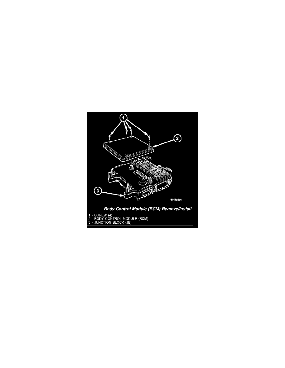
Body Control Module (BCM) Remove/Install
3. Remove the four screws that secure the BCM to the Junction Block (JB).
4. Remove the BCM from the JB.
INSTALLATION
1. Position the Body Control Module (BCM) to the Junction Block (JB) and reconnect them at the JB/BCM interface connector.
2. Install and tighten the screws that secure the BCM to the JB. Tighten the screws to 2 N.m (20 in.lbs.).
3. Reinstall the Junction Block Module (JBM) onto the instrument panel end bracket.
4. Reconnect the negative battery cable.