
Liberty Limited Edition 2WD V6-3.7L VIN K (2002)
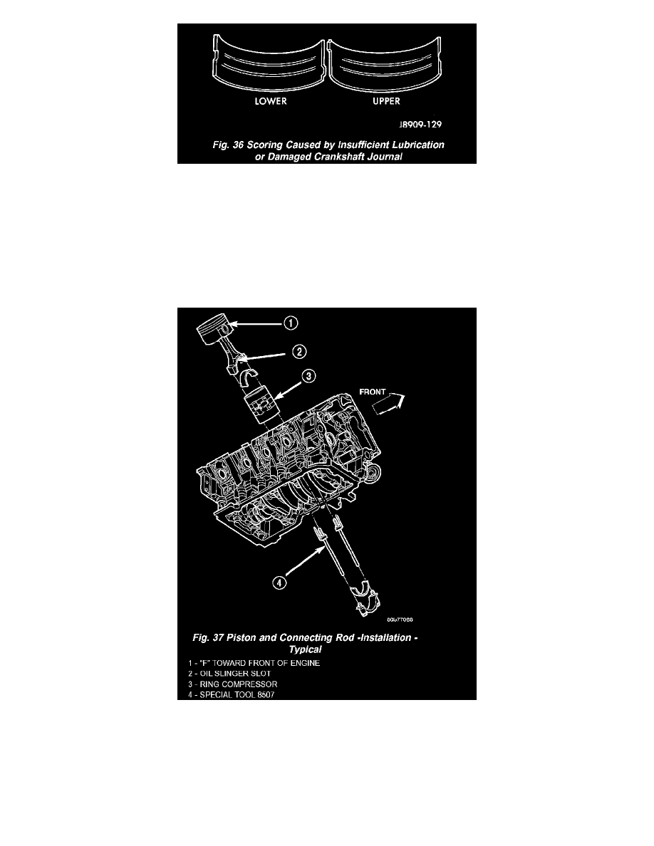
Figure 36
Inspect the connecting rod bearings for scoring and bent alignment tabs (Fig. 34) (Fig. 35). Check the bearings for normal wear patterns, scoring,
grooving, fatigue and pitting (Fig. 36). Replace any bearing that shows abnormal wear. Inspect the connecting rod journals for signs of scoring, nicks
and burrs. Misaligned or bent connecting rods can cause abnormal wear on pistons, piston rings, cylinder walls, connecting rod bearings and
crankshaft connecting rod journals. If wear patterns or damage to any of these components indicate the probability of a misaligned connecting rod,
inspect it for correct rod alignment. Replace misaligned, bent or twisted connecting rods.
1. Wipe the oil from the connecting rod journal.
2. Lubricate the upper bearing insert and install in connecting rod.
3. Use piston ring compressor and Guide Pins Special Tool 8507 (Fig. 37) to install the rod and piston assemblies. The oil slinger slots in the rods
must face front of the engine. The "F"'s near the piston wrist pin bore should point to the front of the engine.
4. Install the lower bearing insert in the bearing cap. The lower insert must be dry. Place strip of Plastigage across full width of the lower insert at the
center of bearing cap. Plastigage must not crumble in use. If brittle, obtain fresh stock.
5. Install bearing cap and connecting rod on the journal and tighten bolts to 27 Nm (20 ft. lbs.) plus a 90 degree turn. DO NOT rotate crankshaft.
Plastigage will smear, resulting in inaccurate indication.