
Liberty Sport 2WD L4-2.4L VIN 1 (2002)
Shift Indicator: Service and Repair
REMOVAL
WARNING: ON VEHICLES EQUIPPED WITH AIRBAGS, DISABLE THE SUPPLEMENTAL RESTRAINT SYSTEM BEFORE
ATTEMPTING ANY STEERING WHEEL, STEERING COLUMN, DRIVER AIRBAG, PASSENGER AIRBAG, SEAT BELT
TENSIONER, FRONT IMPACT SENSORS, SIDE CURTAIN AIRBAG, OR INSTRUMENT PANEL COMPONENT DIAGNOSIS OR
SERVICE. DISCONNECT AND ISOLATE THE BATTERY NEGATIVE (GROUND) CABLE, THEN WAIT TWO MINUTES FOR THE
SYSTEM CAPACITOR TO DISCHARGE BEFORE PERFORMING FURTHER DIAGNOSIS OR SERVICE. THIS IS THE ONLY SURE
WAY TO DISABLE THE SUPPLEMENTAL RESTRAINT SYSTEM. FAILURE TO TAKE THE PROPER PRECAUTIONS COULD
RESULT IN ACCIDENTAL AIRBAG DEPLOYMENT AND POSSIBLE PERSONAL INJURY.
1. Disconnect and isolate the battery negative cable.
2. Remove the center console from the floor panel transmission tunnel.
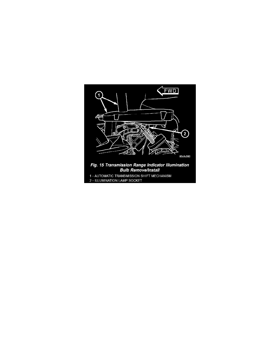
Fig.15 Transmission Range Indicator Illumination Bulb Remove/Install
3. From the left side of the vehicle, reach between transmission range indicator and the floor panel transmission tunnel to grasp the illumination lamp
socket (Fig. 15).
4. Rotate the transmission range indicator illumination lamp socket counterclockwise about 30 degrees on the bottom of the range indicator.
5. Pull the transmission range indicator illumination lamp socket and bulb unit straight out of the bulb mounting hole in the bottom of the indicator.
6. Pull the transmission range indicator illumination lamp bulb straight out of the socket.
INSTALLATION
WARNING: ON VEHICLES EQUIPPED WITH AIRBAGS, DISABLE THE SUPPLEMENTAL RESTRAINT SYSTEM BEFORE
ATTEMPTING ANY STEERING WHEEL, STEERING COLUMN, DRIVER AIRBAG, PASSENGER AIRBAG, SEAT BELT
TENSIONER, FRONT IMPACT SENSORS, SIDE CURTAIN AIRBAG, OR INSTRUMENT PANEL COMPONENT DIAGNOSIS OR
SERVICE. DISCONNECT AND ISOLATE THE, BATTERY NEGATIVE (GROUND) CABLE, THEN WAIT TWO MINUTES FOR THE
SYSTEM CAPACITOR TO DISCHARGE BEFORE PERFORMING FURTHER DIAGNOSIS OR SERVICE. THIS IS THE ONLY SURE
WAY TO DISABLE THE SUPPLEMENTAL RESTRAINT SYSTEM. FAILURE TO TAKE THE PROPER PRECAUTIONS COULD
RESULT IN ACCIDENTAL AIRBAG DEPLOYMENT AND POSSIBLE PERSONAL INJURY.
CAUTION: Always use the correct bulb size and type for replacement. An incorrect bulb size or type may overheat and cause damage to the lamp,
the socket andlor the lamp wiring.
1. Align the base of the transmission range indicator illumination lamp bulb with the receptacle in the lamp socket.
2. Push the transmission range indicator illumination lamp bulb straight into the lamp socket until it is firmly seated.
3. Align the transmission range indicator illumination lamp socket and bulb unit with the mounting hole on the bottom of the indicator (Fig. 15).
4. Push the transmission range indicator illumination lamp socket and bulb unit straight into the bottom of the indicator until it is firmly seated.
5. Rotate the transmission range indicator illumination lamp socket clockwise about 30 degrees on the bottom of the indicator.
6. Reinstall the center console onto the floor panel transmission tunnel.
7. Reconnect the battery negative cable.