
Liberty Sport 2WD L4-2.4L VIN 1 (2002)
Horn Switch: Testing and Inspection
For complete circuit diagrams, refer to the appropriate wiring information. The wiring information includes wiring diagrams, proper wire and connector
repair procedures, details of wire harness routing and retention, connector pin-out information and location views for the various wire harness
connectors, splices and grounds.
WARNING: DISABLE THE AIRBAG SYSTEM BEFORE ATTEMPTING ANY STEERING WHEEL, STEERING COLUMN, SEAT BELT
TENSIONER, SIDE AIRBAG, OR INSTRUMENT PANEL COMPONENT DIAGNOSIS OR SERVICE. DISCONNECT AND ISOLATE
THE BATTERY NEGATIVE (GROUND) CABLE, THEN WAIT TWO MINUTES FOR THE AIRBAG SYSTEM CAPACITOR TO
DISCHARGE BEFORE PERFORMING FURTHER DIAGNOSIS OR SERVICE. THIS IS THE ONLY SURE WAY TO DISABLE THE
AIRBAG SYSTEM. FAILURE TO TAKE THE PROPER PRECAUTIONS COULD RESULT IN ACCIDENTAL AIRBAG DEPLOYMENT
AND POSSIBLE PERSONAL INJURY.
1. Disconnect and isolate the battery negative cable.
2. Remove the steering column opening cover.
3. Check for continuity between the metal steering column jacket and a good ground. There should be continuity If OK, go to Step 4.
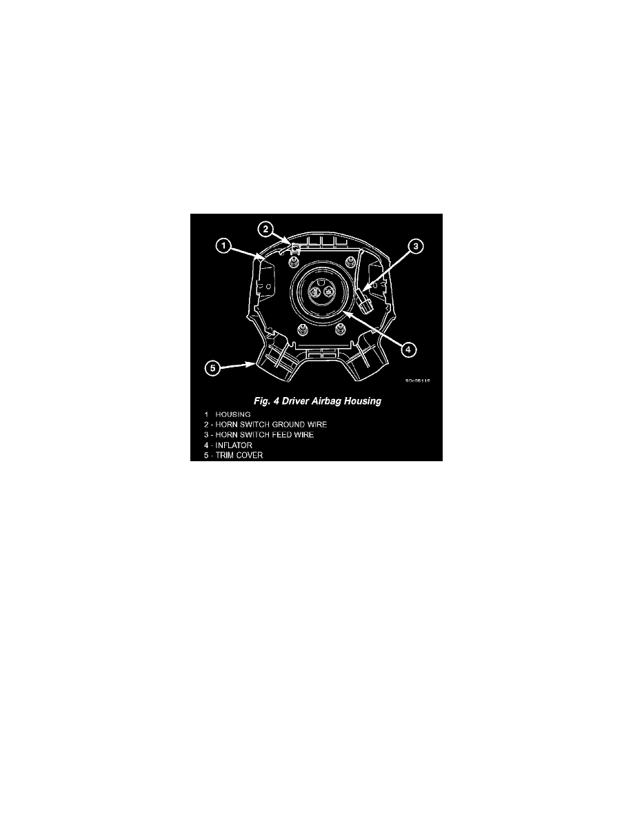
Fig.4 Driver Airbag Housing
4. Remove the driver side airbag module from the steering wheel (Refer to RESTRAINTS/DRIVER AIRBAG - REMOVAL). Disconnect the horn
switch wire harness connectors from the driver side airbag module.
5. Remove the horn relay from the Junction Block (JB). Check for continuity between the steering column half of the horn switch feed wire harness
connector and a good ground. There should be no continuity. If OK, go to Step 6. If not OK, repair the shorted horn relay control circuit to the
horn relay in the Junction Block as required.
6. Check for continuity between the steering column half of the horn switch feed wire harness connector and the horn relay control circuit cavity for
the horn relay in the Junction Block. There should be continuity. If OK, go to Step 7. If not OK, repair the open horn relay control circuit to the
horn relay in the Junction Block as required.
7. Check for continuity between the horn switch feed wire and the horn switch ground wire on the driver side airbag module. There should be no
continuity. If OK, go to Step 8. If not OK, replace the faulty horn switch.
8. Depress the center of the driver side airbag module trim cover and check for continuity between the horn switch feed wire and the horn switch
ground wire on the driver side airbag module. There should now be continuity. If not OK, replace the faulty horn switch (Refer to
RESTRAINTS/DRIVER/AIRBAG - REMOVAL).