
Liberty Sport 2WD L4-2.4L VIN 1 (2002)
Brake Light Switch: Service and Repair
REMOVAL
WARNING: ON VEHICLES EQUIPPED WITH AIRBAGS, DISABLE THE SUPPLEMENTAL RESTRAINT SYSTEM BEFORE
ATTEMPTING ANY STEERING WHEEL, STEERING COLUMN, DRIVER AIRBAG, PASSENGER AIRBAG, SEAT BELT
TENSIONER, FRONT IMPACT SENSORS, SIDE CURTAIN AIRBAG, OR INSTRUMENT PANEL COMPONENT DIAGNOSIS OR
SERVICE. DISCONNECT AND ISOLATE THE BATTERY NEGATIVE (GROUND) CABLE, THEN WAIT TWO MINUTES FOR THE
SYSTEM CAPACITOR TO DISCHARGE BEFORE PERFORMING FURTHER DIAGNOSIS OR SERVICE. THIS IS THE ONLY SURE
WAY TO DISABLE THE SUPPLEMENTAL RESTRAINT SYSTEM. FAILURE TO TAKE THE PROPER PRECAUTIONS COULD
RESULT IN ACCIDENTAL AIRBAG DEPLOYMENT AND POSSIBLE PERSONAL INJURY.
1. Disconnect and isolate the battery negative cable.
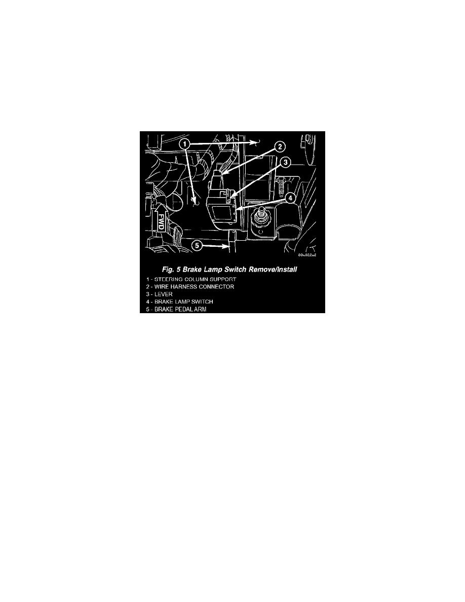
Fig.5 Brake Lamp Switch Remove/Install
2. Disconnect the instrument panel wire harness connector for the brake lamp switch from the switch connector receptacle.
3. Grasp the brake lamp switch housing firmly and rotate the switch counter-clockwise about 30 degrees to align the tabs on the locking collar with
the keyed mounting hole in the steering column support bracket.
4. Pull the switch straight back from the mounting hole to remove it from the steering column support bracket.
5. Discard the removed brake lamp switch.
CAUTION: Always replace a removed brake lamp switch with a new unit. This is a one time component and is not intended for reinstallation.
INSTALLATION
CAUTION: Always replace a removed brake lamp switch with a new unit. This is a one time component and is not intended for reinstallation.
1. While holding the brake pedal depressed, align the tabs on the brake lamp switch locking collar with the keyed mounting hole in the steering
column support bracket.
2. Still holding the brake pedal depressed, insert the tabs on the brake lamp switch housing through the keyed mounting hole in the steering column
support bracket until the switch is firmly seated against the bracket.
3. Still holding the brake pedal depressed, rotate the switch clockwise about 30 degrees to lock the tabs on the brake lamp switch locking collar to the
keyed mounting hole in the steering column support bracket.
4. Release the brake pedal.
CAUTION: Do not pull up on the brake pedal before the switch plunger adjustment has been completed.
5. Rotate the plunger adjustment release lever clockwise until it locks into place parallel to the brake lamp switch connector receptacle. This action
will set the switch plunger length to a final adjustment position and cannot be undone. If not performed properly the first time, a new brake lamp
switch must be installed.
6. Reconnect the instrument panel wire harness connector for the brake lamp switch to the switch connector receptacle.
7. Reconnect the battery negative cable.