
Liberty Sport 2WD L4-2.4L VIN 1 (2002)
Turn Signal Switch: Description and Operation
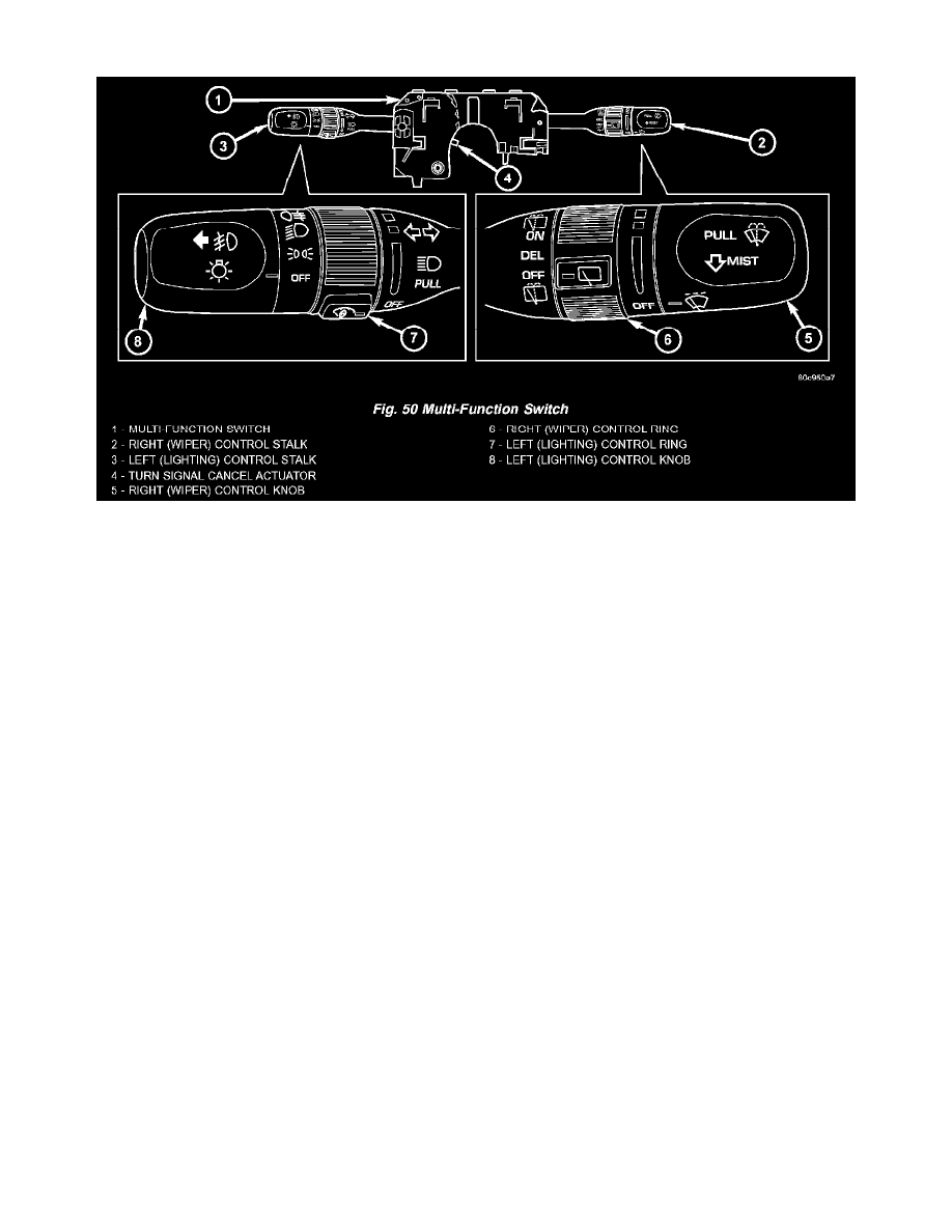
Fig.50 Multi-Function Switch
MULTIFUNCTION SWITCH
The multi-function switch is located on the steering column, just below the steering wheel. The only visible components of the multi function switch are
two levers, or control stalks that extend through dedicated openings in each side of the steering column shrouds. The remainder of the switch, its
mounting provisions, and its electrical connections are all concealed beneath the steering column shrouds. The switch housing and controls are
constructed of molded black plastic. A saddle-like formation in the center of the multi-function switch housing straddles the steering column tube just
below the column lock housing, and two posts integral to the lower surface of the switch housing engage two holes on the forward-facing side of the lock
housing. Two integral ledge-like locating tabs near the top of the rearward facing switch housing surface are supported and located by two upright
stanchions that extend upward from the top of the lock housing. Also on the rearward facing switch housing surface near the center, an integral ledge-
like mounting tab rests on a similar ledge-like tab that extends from each side of the steering column lock housing. When the steering column shrouds are
installed on the column, the switch mounting tabs are clamped along with the mounting tabs of the clockspring between the integral mounting stanchions
of the upper shroud and the lock housing tabs, and are secured to the steering column lock housing by the same two screws that secure the two shroud
halves to each other and the column.
There are several versions of the multi-function switch to support both optional equipment and equipment that is required only in certain markets. Each
multi-function switch control stalk has both white nomenclature and International Control and Display Symbol graphics applied to it, which clearly
identify its many functions. Each control stalk has a control knob on its end with a flattened face to allow it to be easily rotated. On vehicles equipped
with optional front fog lamps, the knob on the end of left control stalk can also be pulled outward to select those lamps. Each control stalk also features a
knurled control ring located just below the control knob. The left control stalk is dedicated to providing driver controls for the interior and exterior
lighting systems, while the right control stalk is dedicated to providing driver controls for the front and rear wiper systems. Two integral connector
receptacles on the forward facing surface of the multi-function switch housing connect the switch two the vehicle electrical system through two take outs
and connectors of the instrument panel wire harness. The left connector receptacle contains nine terminal pins for the lighting control circuits of the
switch, while the right connector receptacle contains six terminal pins for the wiper control circuits of the switch. The multi-function switch cannot be
adjusted or repaired and, if faulty or damaged, it must be replaced.
LEFT CONTROL STALK The left (lighting) control stalk of the multi-function switch supports the following functions and features:
-
Front Fog Lamps - For vehicles so equipped, the internal circuitry and hardware of the multi- function switch left (lighting) control stalk
provide detent switching for the optional front fog lamps.
-
Headlamps - The internal circuitry and hardware of the multi-function switch left (lighting) control stalk provide detent switching for the
headlamps.
-
Headlamp Beam Selection - The internal circuitry and hardware of the multi-function switch left (lighting) control stalk provide detent
switching for selection of the headlamp high or low beams.
-
Headlamp Optical Horn - The internal circuitry and hardware of the multi-function switch left (lighting) control stalk includes momentary