
Liberty Sport 2WD L4-2.4L VIN 1 (2002)
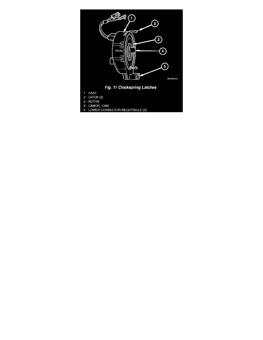
Fig.11 Clockspring Latches
The clockspring assembly is secured with two integral plastic latches onto the upper steering column housing near the top of the steering column behind
the steering wheel. The clockspring consists of a flat, round molded plastic case with a stubby tail that hangs below the steering column and contains two
connector receptacles that face toward the instrument panel. Within the plastic housing is a spool-like molded plastic rotor with a large exposed hub and
several plastic rollers. The upper surface of the rotor hub has a large center hole, a release button, a clear plastic inspection window, two short pigtail
wires with connectors, and a connector receptacle that faces toward the steering wheel. Two versions of the clockspring are used on this model, one is a
seven circuit unit for vehicles not equipped with optional remote radio switches on the steering wheel and can be visually identified by the use of yellow
heat-shrink tubing on the pigtail wires, while the other is a nine circuit unit for vehicles with remote radio switches and can be visually identified by the
use of black heat-shrink tubing on the pigtail wires.
A rubber bumper block is located on each side of the tower formation that contains the connector receptacle and pigtail wires on the upper surface of the
rotor hub. The lower surface of the rotor hub has a molded plastic turn signal cancel cam with a single lobe that is integral to the rotor. Within the plastic
case and wound around the rotor spool is a long ribbon-like tape that consists of several thin copper wire leads sandwiched between two thin plastic
membranes. The outer end of the tape terminates at the connector receptacles that face the instrument panel, while the inner end of the tape terminates at
the pigtail wires and connector receptacle on the hub of the clockspring rotor that face the steering wheel.
Service replacement clocksprings are shipped precentered and with a molded plastic shield that snaps onto the rotor over the release button. The release
button secures the centered clockspring rotor to the clockspring case and the shield prevents the release button from being inadvertently depressed during
shipment and handling, but the shield must be removed from the clockspring after it is installed on the steering column. (Refer to
RESTRAINTS/CLOCKSPRING - STANDARD PROCEDURE - CLOCKSPRING CENTERING).
The clockspring cannot be repaired. If the clockspring is faulty, damaged, or if the driver airbag has been deployed, the clockspring must be replaced.
The clockspring is a mechanical electrical circuit component that is used to provide continuous electrical continuity between the fixed instrument panel
wire harness and the electrical components mounted on or in the rotating steering wheel. On this model the rotating electrical components include the
driver airbag, the horn switch, the speed control switches, and the remote radio switches, if the vehicle is so equipped. The clockspring case is positioned
and secured to the upper steering column housing near the top of the steering column. The connector receptacles on the tail of the fixed clockspring case
connect the clockspring to the vehicle electrical system through two take outs with connectors from the instrument panel wire harness. The clockspring
rotor is movable and is keyed by the tower formation that is molded onto the upper surface of the rotor hub to an opening that is cast into the steering
wheel armature. Rubber bumper blocks on either side of the clockspring tower formation eliminate contact noise between the clockspring tower and the
steering wheel. The lobe of the turn signal cancel cam on the lower surface of the clockspring rotor hub contacts a turn signal cancel actuator of the
multi-function switch to provide automatic turn signal cancellation. The yellow-sleeved pigtail wires on the upper surface of the clockspring rotor
connect the clockspring to the driver airbag, while a steering wheel wire harness connects the connector receptacle on the upper surface of the
clockspring rotor to the horn switch and, if the vehicle is so equipped, to the optional speed control switches and remote radio switches on the steering
wheel.
Like the clockspring in a timepiece, the clockspring tape has travel limits and can be damaged by being wound too tightly during full stop-to-stop
steering wheel rotation. To prevent this from occurring, the clockspring is centered when it is installed on the steering column. Centering the clockspring
indexes the clockspring tape to the movable steering components so that the tape can operate within its designed travel limits. However, if the
clockspring is removed from the steering column or if the steering shaft is disconnected from the steering gear, the clockspring spool can change position
relative to the movable steering components and must be re-centered following completion of the service or the tape may be damaged. Service
replacement clocksprings are shipped pre-centered and with a plastic shield installed over the clockspring release button. This shield should not be