
Liberty Sport 2WD L4-2.4L VIN 1 (2002)
Brake Light Switch: Description and Operation
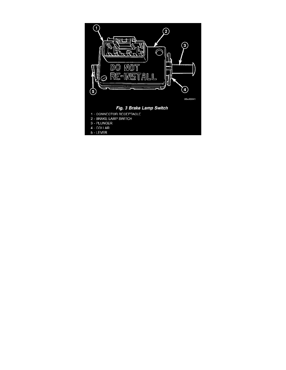
Fig.3 Brake Lamp Switch
The brake lamp switch is a three circuit, spring- loaded plunger actuated switch that is secured to the steering column support bracket under the driver
side of the instrument panel. The brake lamp switch is contained within a rectangular molded plastic housing with an integral connector receptacle
featuring six terminal pins and a red plastic Connector Position Assurance (CPA) lock. The switch is connected to the vehicle electrical system through a
dedicated take out and connector of the instrument panel wire harness. The switch plunger extends through a mounting collar on one end of the switch
housing. The plunger has a one time telescoping self- adjustment feature that is achieved after the switch is installed by moving an adjustment release
lever on the opposite end of the switch housing clockwise, until it locks in a position that is parallel to the connector receptacle. The brake lamp switch
self-adjustment is a one time feature. Once the feature has been used, the switch cannot be readjusted. A "DO NOT RE-INSTALL" warning is molded
into the switch housing below the connector receptacle.
An installed brake lamp switch cannot be readjusted or repaired. If the switch is damaged, faulty, or removed from its mounting position for any reason,
it must be replaced with a new unit.
The brake lamp switch controls three different circuits, one normally open and two normally closed. These circuits are described as follows:
-
Brake Lamp Switch Circuit - A normally open brake lamp switch circuit receives battery current on a fused B(+) circuit from a fuse in the
Junction Block (JB), and supplies battery current to the brake lamps and the Controller Antilock Brake (CAB) on a brake lamp switch output
circuit when the brake pedal is depressed (brake lamp switch plunger released).
-
Brake Lamp Switch Signal Circuit - A normally closed brake lamp switch signal circuit receives a path to ground through a splice block located
in the instrument panel wire harness with an eyelet terminal connector that is secured by a nut to a ground stud on the driver side instrument panel
end bracket near the Junction Block (JB). This circuit supplies a ground input to the Powertrain Control Module (PCM) on a brake lamp switch
sense circuit when the brake pedal is released (brake lamp switch plunger is depressed).
-
Speed Control Circuit - A normally closed speed control circuit receives battery current from the Powertrain Control Module on a speed control
supply circuit, and supplies battery current to the speed control servo solenoids (dump, vacuum, and vent) on a speed control brake switch output
circuit when the speed control system is turned ON and the brake pedal is released (brake lamp switch plunger is depressed).
Concealed within the brake lamp switch housing the components of the self-adjusting brake switch plunger consist of a two-piece telescoping plunger, a
split plunger locking collar, and a release wedge. The release lever has an integral shaft with a wedge that spreads the plunger locking collar to an open
or released position. After the switch is installed and the brake pedal is released, the plunger telescopes to the correct adjustment position. When the
release lever is moved to the release position, the wedge is disengaged from the locking collar causing the collar to apply a clamping pressure to the two
plunger halves fixing the plunger length.
The brake lamp switch can be diagnosed using conventional diagnostic tools and methods.