
Liberty Sport 2WD L4-2.4L VIN 1 (2002)
Starter Relay: Testing and Inspection
The starter relay is located in the Power Distribution Center (PDC) in engine compartment. Refer to label on PDC cover for relay location.
RELAY TEST
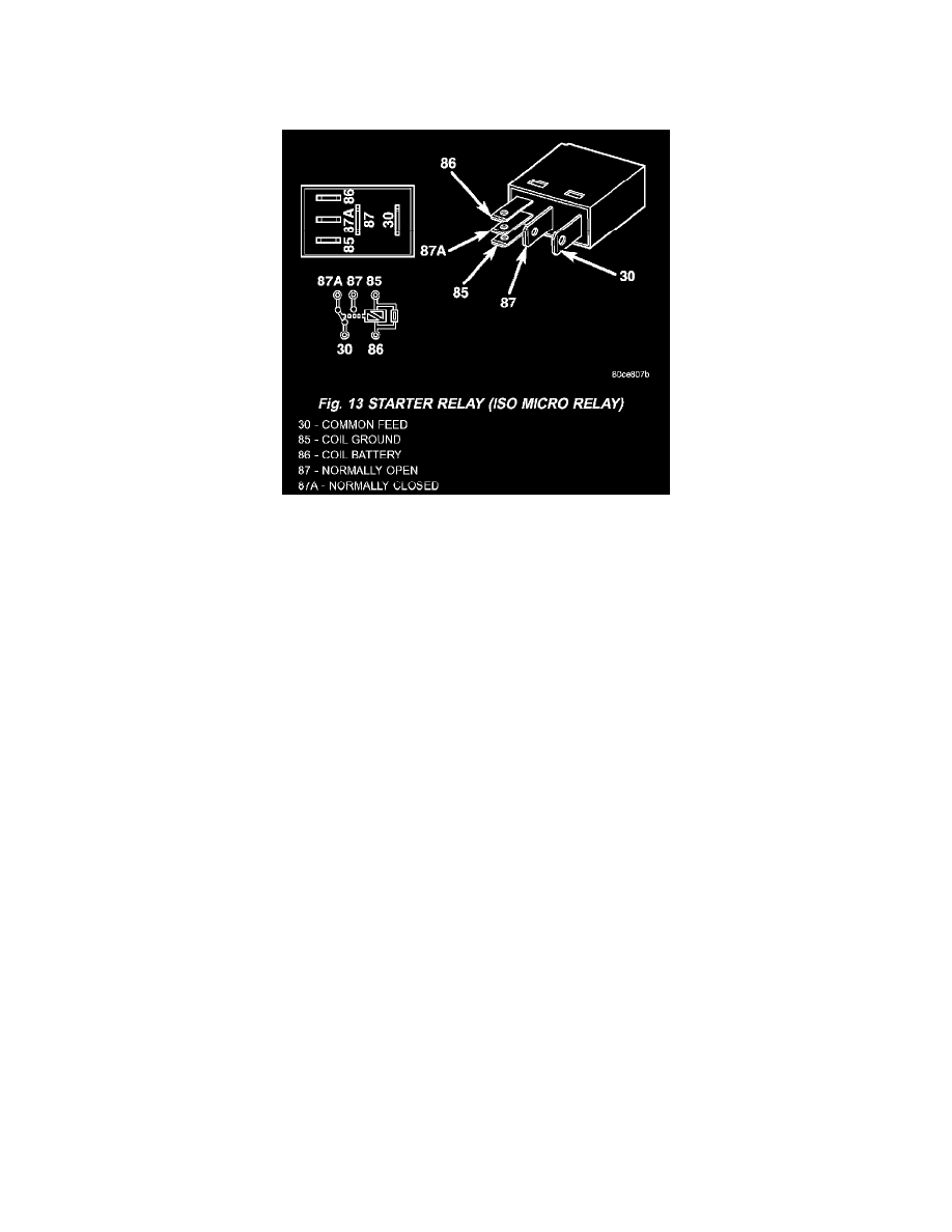
Fig.13 Starter Relay (ISO Micro Relay)
1. Remove starter relay (Fig. 13) from PDC.
2. A relay in de-energized position should have continuity between terminals 87A and 30, and no continuity between terminals 87 and 30. If OK, go
to Step 3. If not OK, replace faulty relay
3. Resistance between terminals 85 and 86 (electromagnet) should be 75 ± 5 ohms. If OK, go to Step 4. If not OK, replace faulty relay.
4. Connect a battery to terminals 85 and 86.There should now be continuity between terminals 30 and 87, and no continuity between terminals 87A
and 30. If OK, perform following Relay Circuit Test. If not OK, replace faulty relay.
RELAY CIRCUIT TEST
1. The relay common feed terminal cavity (30) is connected to battery voltage and should be hot at all times. If OK, go to Step 2. If not OK, repair
open circuit to fused B(+) fuse in PDC as required.
2. The relay normally closed terminal (87A) is connected to terminal 30 in de-energized position, but is not used for this application. Go to Step 3.
3. The relay normally open terminal (87) is connected to common feed terminal (30) in energized position. This terminal supplies battery voltage to
starter solenoid field coil. There should be continuity between cavity for relay terminal 87 and starter solenoid terminal at all times. If OK, go to
Step 4. If not OK, repair open engine starter motor relay output circuit to starter solenoid as required.
4. The coil battery terminal (86) is connected to electromagnet in relay. It is energized when ignition switch is held in Start position. On vehicles with
a manual transmission, the clutch pedal must be blocked in fully depressed position for this test. Check for battery voltage at cavity for relay
terminal 86 with ignition switch in Start position, and no voltage when ignition switch is released to ON position. If OK, go to Step 5. If not OK
with a manual transmission, disconnect clutch pedal position switch wire harness connector and install a jumper wire between two cavities in body
half of connector and check for battery voltage again at cavity for relay terminal 86.If now OK, replace faulty clutch pedal position switch. If still
not OK with a manual transmission or if not OK with an automatic transmission, check for open or shorted fused ignition switch output (start)
circuit to ignition switch and repair as required. If fused ignition switch output (start) circuit is OK, refer to Ignition Switch and Key Lock
Cylinder.
5. The coil ground terminal (85) is connected to electromagnet in relay. On vehicles with manual transmission, it is grounded at all times. On vehicles
with automatic transmission, it is grounded through park/neutral position switch only when gearshift selector lever is in Park or Neutral positions.
Check for continuity to ground at cavity for relay terminal 85.If not OK with a manual transmission, repair open park/neutral position switch sense
circuit to ground as required. If not OK with an automatic transmission, check for open or shorted park/neutral position switch sense circuit to
park/neutral position switch and repair, as required. If park/neutral position switch sense circuit checks OK, refer to Park/Neutral Position Switch.