
Liberty Sport 2WD L4-2.4L VIN 1 (2002)
Heated Glass Element Relay: Testing and Inspection
WARNING: ON VEHICLES EQUIPPED WITH AIRBAGS, DISABLE THE AIRBAG SYSTEM BEFORE ATTEMPTING ANY STEERING
WHEEL, STEERING COLUMN, OR INSTRUMENT PANEL COMPONENT DIAGNOSIS OR SERVICE. DISCONNECT AND ISOLATE
THE BATTERY NEGATIVE (GROUND) CABLE, THEN WAIT TWO MINUTES FOR THE AIRBAG SYSTEM CAPACITOR TO
DISCHARGE BEFORE PERFORMING FURTHER DIAGNOSIS OR SERVICE. THIS IS THE ONLY SURE WAY TO DISABLE THE
AIRBAG SYSTEM. FAILURE TO TAKE THE PROPER PRECAUTIONS COULD RESULT IN AN ACCIDENTAL AIRBAG
DEPLOYMENT AND POSSIBLE PERSONAL INJURY.
Defogger Relay
RELAY TEST
The defogger relay is located in the junction block, on the left side of the instrument panel inboard to the center of the vehicle must to the right and
above the brake pedal or behind the knee blocker). Remove the defogger relay from the junction block to perform the following tests:
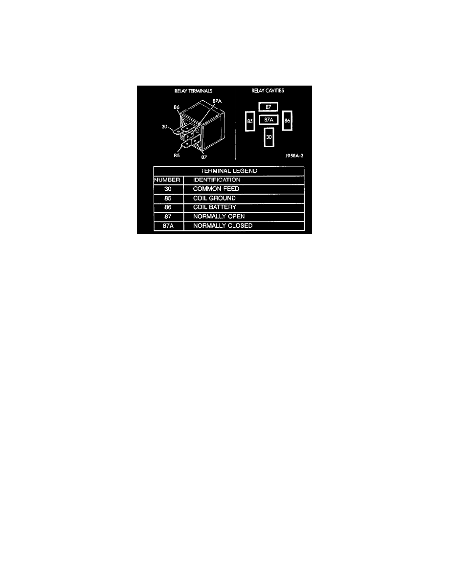
1. A relay in the de-energized position should have continuity between terminals 87A and 30, and no continuity between terminals 87 and 30. If OK,
go to Step 2. If not OK, replace the faulty relay
2. Resistance between terminals 85 and 86 (electromagnet) should be 60.7 to 80.3 ohms. If OK, go to Step 3. If not OK, replace the faulty relay.
3. Connect a battery to terminals 85 and 86.There should now be continuity between terminals 30 and 87, and no continuity between terminals 87A
and 30. If OK, see the Relay Circuit Test in this group. If not OK, replace the faulty relay
RELAY CIRCUIT TEST
1. The relay common feed terminal cavity (30) is connected to battery voltage and should be hot at all times. If OK, go to Step 2. If not OK, repair
the open circuit to the PDC fuse as required.
2. The relay normally closed terminal (87A) is connected to terminal 30 in the de-energized position, but is not used for this application. Go to Step
3.
3. The relay normally open terminal (87) is connected to the common feed terminal (30) in the energized position. This terminal supplies battery
voltage to the rear glass and outside rear view mirror heating grids and the defogger switch indicator lamp. There should be continuity between the
cavity for relay terminal 87 and the rear window defogger relay output circuit cavities of the rear glass heating grid connector, both outside rear
view mirror heating grid connectors, and the defogger switch connector at all times. If OK, go to Step 4. If not OK, repair the open circuit(s) as
required.
4. The coil ground terminal (85) is connected to the electromagnet in the relay. This terminal is provided with ground by the instrument cluster rear
window defogger timer and logic circuitry to energize the defogger relay. There should be continuity to ground at the cavity for relay terminal 85
when the defogger switch is turned ON. However, with the defogger relay removed, the defogger switch indicator lamp will not light to show that
the defogger system is turned ON. Be certain that you depress the defogger switch at least twice to confirm that the system is turned on during this
test. If OK, go to Step 5. If not OK, repair the open circuit to the HVAC control head as required.
5. The coil battery terminal (86) is connected to the electromagnet in the relay. It is connected to fused ignition switch output voltage and should be
hot when the ignition switch is in the run position. Check for battery voltage at the cavity for relay terminal 86 with the ignition switch in the run
position. If OK, see the diagnosis for Instrument Cluster in this group. If not OK, repair the open circuit to the fuse in the junction block as
required.