
Liberty Sport 4WD L4-2.4L VIN 1 (2002)
Remote Switch: Description and Operation
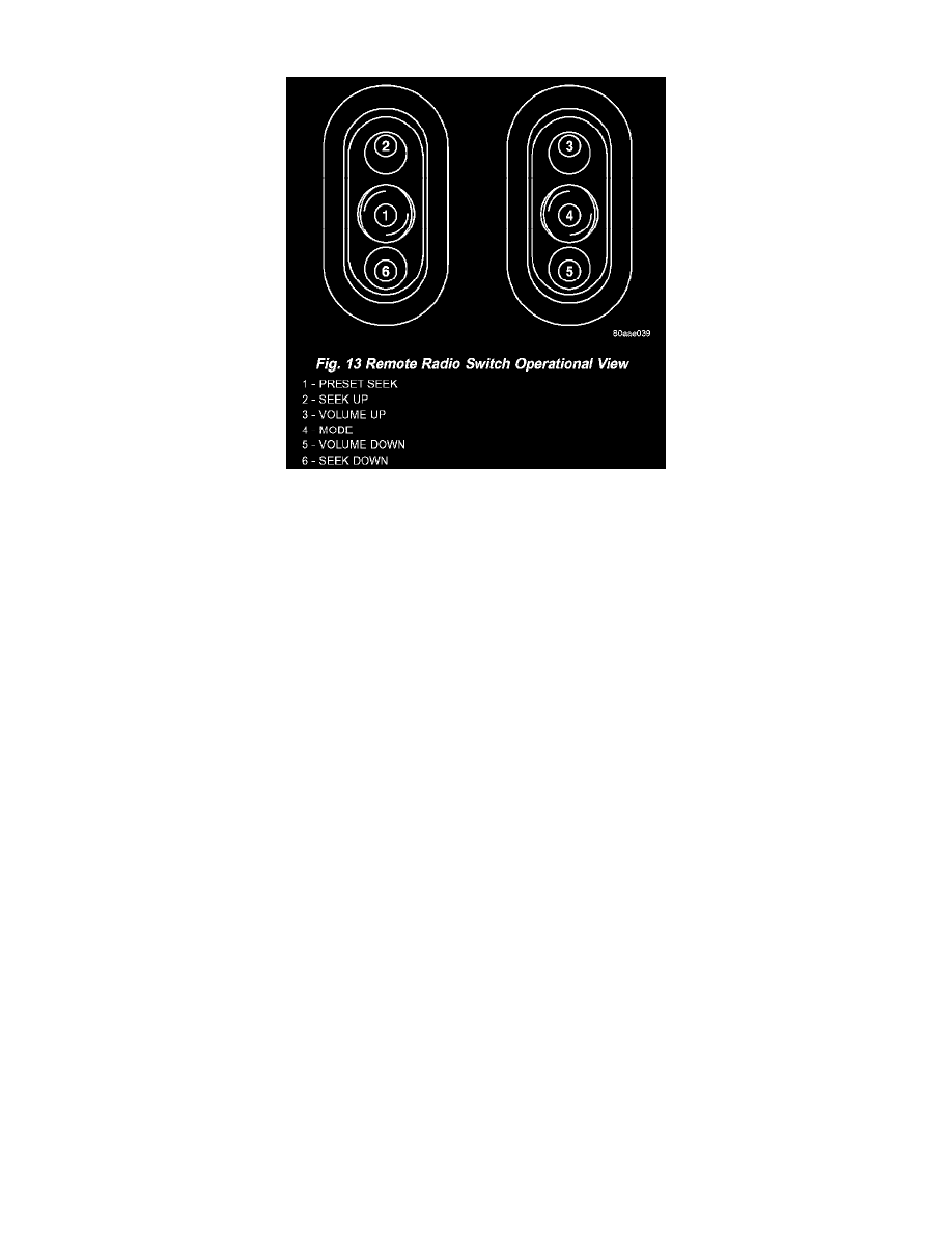
Fig.13 Remote Radio Switch Operational View
REMOTE RADIO SWITCHES
A remote radio control switch option is available on some models. Two rocker-type switches are mounted on the back (instrument panel side) of the
steering wheel spokes. The switch on the left spoke is the SEEK switch and has Seek Up, Seek Down, and Preset station advance functions. The
switch on the right spoke is the VOLUME control switch and has Volume Up, and Volume Down functions. The switch on the right spoke also
includes a MODE control that allows the driver to sequentially select AM radio, FM radio, Cassette Player, CD player or CD changer (if equipped).
The six switches in the two remote radio switch units are normally open, resistor multiplexed momentary switches that are hard wired to the Body
Control Module (BCM) through the clockspring. The BCM sends a five volt reference signal to both switch units on one circuit, and senses the status
of all of the switches by reading the voltage drop on a second circuit.
When the BCM senses an input (voltage drop) from any one of the remote radio switches, it sends the proper switch status messages on the
Programmable Communication Interface (PCI) data bus network to the radio receiver. The electronic circuitry within the radio receiver is
programmed to respond to these remote radio switch status messages by adjusting the radio settings as requested. For diagnosis of the BCM or the PCI
data bus, the use of a DRB scan tool and the proper Diagnostic Procedures are recommended.
For more information on the features and control functions for each of the remote radio switches, refer to the owner's manual.