
Liberty Sport 4WD L4-2.4L VIN 1 (2002)
UNIVERSAL TRANSMITTER
On some KJ models a Universal Transmitter transceiver is standard factory-installed equipment. The universal transmitter transceiver is integral to
the Compass Mini-Trip Computer (CMTC), which is located in the overhead console. The only visible component of the universal transmitter are
the three transmitter push buttons (Fig. 7) centered between the four CMTC push buttons located just rearward of the CMTC display screen in the
overhead console. The three universal transmitter push buttons are identified with one, two or three light indicators so that they be easily identified
by sight or by feel.
Each of the three universal transmitter push buttons controls an independent radio transmitter channel. Each of these three channels can be trained
to transmit a different radio frequency signal for the remote operation of garage door openers, motorized gate openers, home or office lighting,
security systems or just about any other device that can be equipped with a radio receiver in the 286 to 399 MegaHertz (MHz) frequency range
for remote operation. The universal transmitter is capable of operating systems using either rolling code or non-rolling code technology.
The CMTC module displays messages and a small house-shaped icon with one, two or three dots corresponding to the three transmitter buttons to
indicate the status of the Universal Transmitter.
The Universal Transmitter cannot be repaired, and is available for service only as a unit with the CMTC module. This unit includes the push
button switches and the plastic module and display lens. If any of these components is faulty or damaged, the complete CMTC module must be
replaced.
The universal transmitter operates on a non- switched source of battery current so the unit will remain functional, regardless of the ignition switch
position. For more information on the features, programming procedures and operation of the universal transmitter, see the owner's manual in the
vehicle glove box.
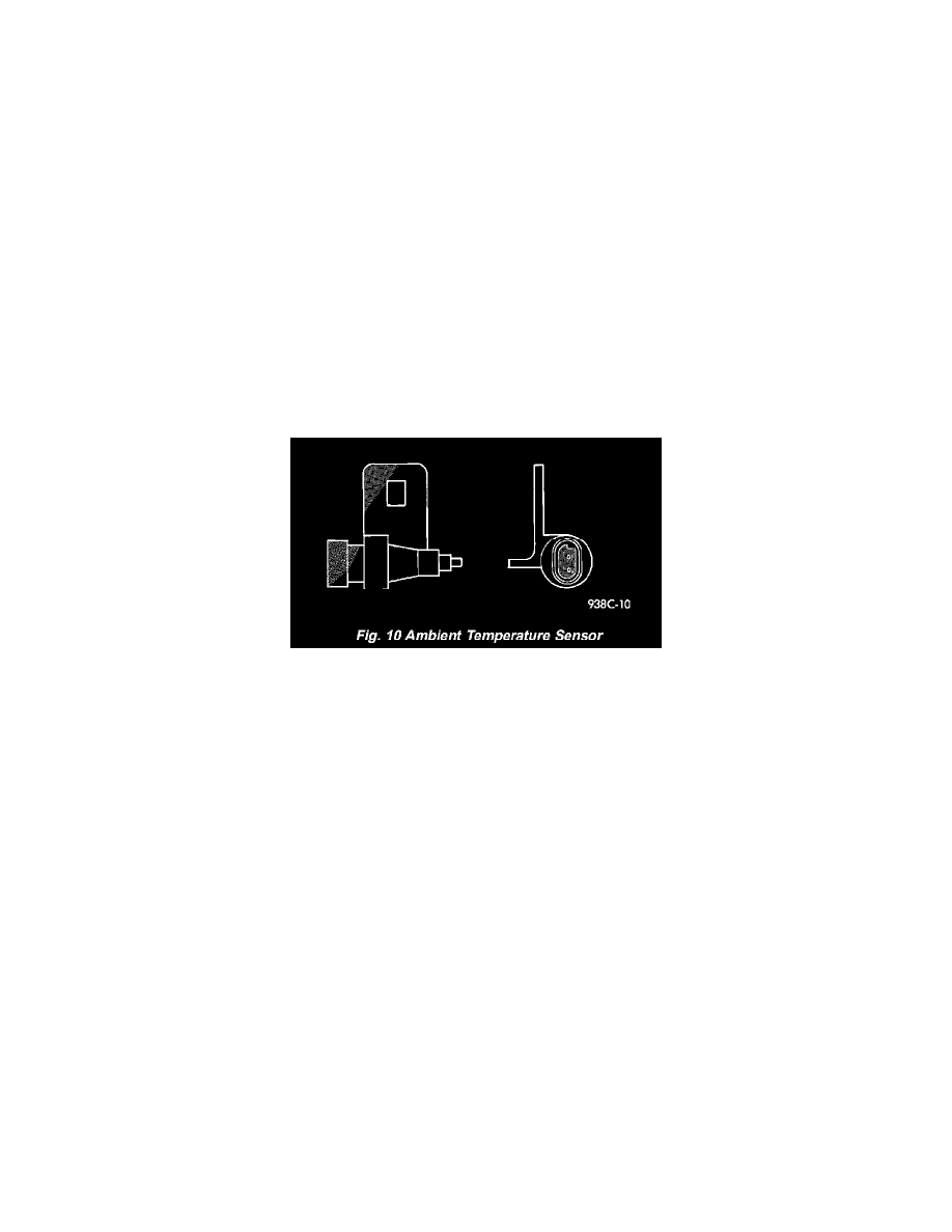
Fig. 10 Ambient Temperature Sensor
AMBIENT TEMP SENSOR
Ambient air temperature is monitored by the Compass Mini-Trip Computer (CMTC) through ambient temperature sensor messages received from
the Body Control Module (BCM) over the Programmable Communications Interface (PCI) data bus network. The BCM receives a hard wired
input from the ambient temperature sensor. The ambient temperature sensor (Fig. 8) is a variable resistor mounted in front the radiator, behind the
grille, near the center of the vehicle.
Refer to Body Control Module in Electronic Control Modules. For complete circuit diagrams, refer to the appropriate wiring information. The
ambient temperature sensor cannot be adjusted or repaired and, if faulty or damaged, it must be replaced.
The ambient temperature sensor is a variable resistor that operates on a five-volt reference signal sent to it by the BCM. The resistance in the
sensor changes as temperature changes, changing the temperature sensor signal circuit voltage to the BCM. Based upon the resistance in the
sensor, the BCM senses a specific voltage on the temperature sensor signal circuit, which it is programmed to correspond to a specific temperature.
The BCM then sends the proper ambient temperature messages to the CMTC over the PCI data bus.
The thermometer function is supported by the ambient temperature sensor, a wiring circuit, the Body Control Module (BCM), the Programmable
Communications Interface (PCI) data bus, and a portion of the Compass Mini-Trip Computer module.
The ambient temperature sensor circuit can also be diagnosed by referring to Diagnosis and Testing - Ambient Temperature Sensor, and Diagnosis
and Testing - Ambient Temperature Sensor Circuit. If the temperature sensor and circuit are confirmed to be OK, but the temperature display is
inoperative or incorrect, refer to Diagnosis and Testing - Compass Mini-Trip Computer in this section. For complete circuit diagrams, refer to the
appropriate wiring information.