
Liberty Sport 4WD L4-2.4L VIN 1 (2002)
REMOVAL - RHD
The following junction block removal procedure applies to Right Hand Drive (RHD) vehicles only
1. Disconnect and isolate the negative battery cable.
2. Remove the right end cap from the instrument panel.
3. Unsnap and remove the right outboard trim bezel from the instrument panel Located just to the right of the steering column.
4. Remove the steering column opening cover.
5. Remove the right cowl trim panel from the vehicle.
6. Remove the courtesy lamp from under the right side of the instrument panel. This will allow sufficient room to remove the junction block from
under the instrument panel.
7. Working through the steering column opening cover, remove the three bulkhead and two body controller electrical connectors from the junction
block assembly
8. Remove the two ground wires from the right lower kick panel area. Located directly behind the kick trim panel. This will allow sufficient room to
remove the junction block from under the instrument panel.
9. Remove the upper and forward most (in relation to the vehicle) group of relays from the junction block. This will allow sufficient room to remove
the junction block from under the instrument panel.
10. Remove the four junction block retaining screws and remove the junction block from under the instrument panel. It will be necessary to position
the under instrument panel wire harness out of the way to remove the junction block.
INSTALLATION - RHD
1. Position the junction block and install the four junction block retaining screws.
2. Install the upper and forward most group of relays in the junction block.
3. Install the two ground wires on the right lower kick panel area.
4. Working through the steering column opening cover, install the three bulkhead and two body controller electrical connectors on the junction block
assembly.
5. Install the courtesy lamp under the right side of the instrument panel.
6. Install the right cowl trim panel on the vehicle.
7. Install the steering column opening cover
8. Install the right outboard trim bezel on the instrument panel.
9. Install the right end cap on the instrument panel.
10. Connect the negative battery cable.
PDC B+ Terminal Module
Disassembly and Assembly
REMOVAL
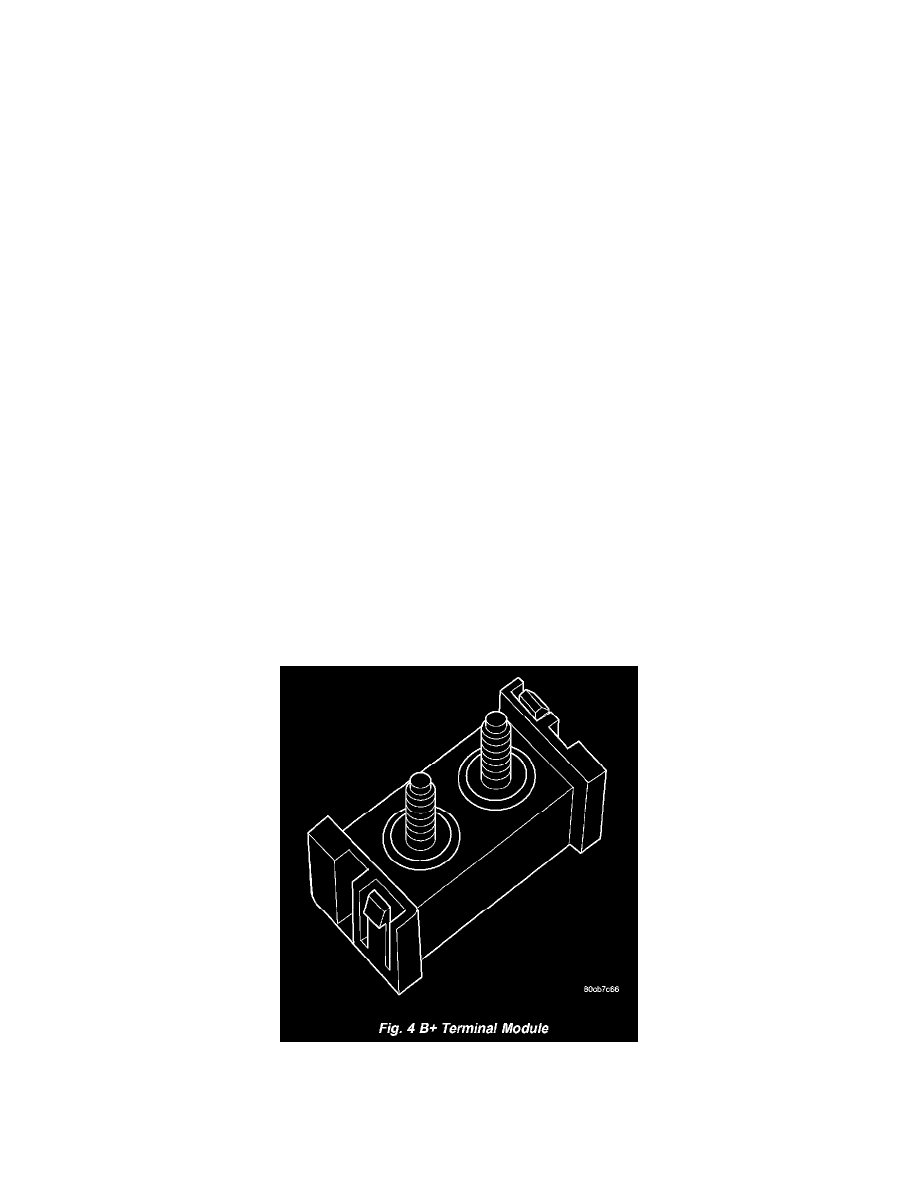
Fig. 4 B+ Terminal Module
The Power Distribution Center (PDC) cover, the PDC housing lower cover, the PDC relay wedges, the PDC mini fuse wedge, the PDC relay cassettes
and the PDC B(+) terminal stud module are available for service replacement. The PDC cover can be simply unlatched and removed from the PDC
housing without the PDC being removed or disassembled. Service of the remaining PDC components requires that the PDC be removed from its