
Patriot 2WD L4-2.4L (2009)
Camshaft: Description and Operation
Camshaft - Description
DESCRIPTIONS
Both camshafts have five bearing journal surfaces and two cam lobes per cylinder. The two front journals are larger to allow for feeding oil to the
variable valve timing (VVT) camshaft phasers. Flanges on the third smaller journal control camshaft end play. At the rear of each camshaft is an integral
cam sensor target.
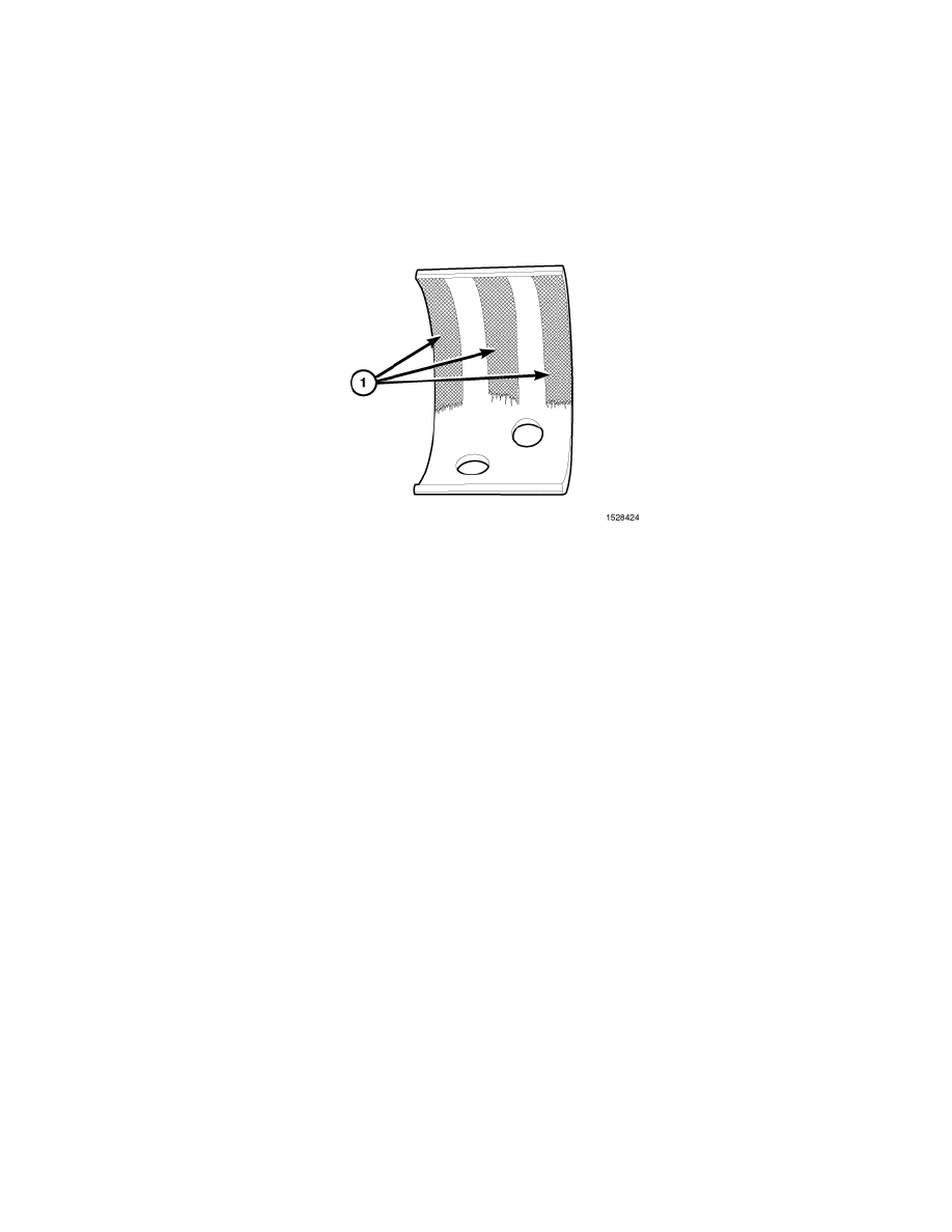
CAMSHAFT BEARING CAPS
The front cam bearing cap spans both camshafts, and includes dowels for precise alignment. The front exhaust camshaft journal has a select fit bearing
insert. This bearing is required to seal the oil passage to the camshaft phaser, because a portion of the lower bearing saddle is machined away for head
bolt access. The select fit is required to minimize bearing clearance and oil leakage. An exhaust bearing grade (1,2,or 3) is stamped into the front bearing
cap adjacent to the exhaust cam journal. The bearings are also marked with the corresponding grade markings. If the bearing is replaced, the same grade
must be used. Due to the unique purpose of this bearing, it may appear to have uneven wear patterns (1). Maximum wear of 0.05 mm (.002 in.) is
acceptable. Unless the wear is excessive it is no cause for concern and the bearing should not be replaced. Cam bearing inspection should not be the sole
reason for removal of the exhaust camshaft. The upper cam bearing may be replaced if the front bearing cap is removed. The lower cam bearing should
be replaced if the camshaft is removed due to a failure of a component within the cylinder head.
The front intake cam journal has a full lower bearing saddle, and therefore, no bearing insert is required.
All small bearing caps have a formed-in arrow to assist in assembly. All small bearing cap arrows must point towards the center of the cylinder head. The
small bearing caps are marked for position during the manufacturing process, and must be reinstalled in their original position.
The #1 small cap includes a passage to direct oil from the cylinder head oil gallery to the #1 small bearing journal, and into the camshaft as well. The
hollow camshaft then distributes oil to the remainder of the small journals. Oil flowing out of each cam journal lubricates the valve tappets.
The #3 small cap is machined at the front and rear face to control camshaft end-play. This cap has dowels for precise alignment.