
Wagoneer L4-150 2.5L VIN E TBI (1990)
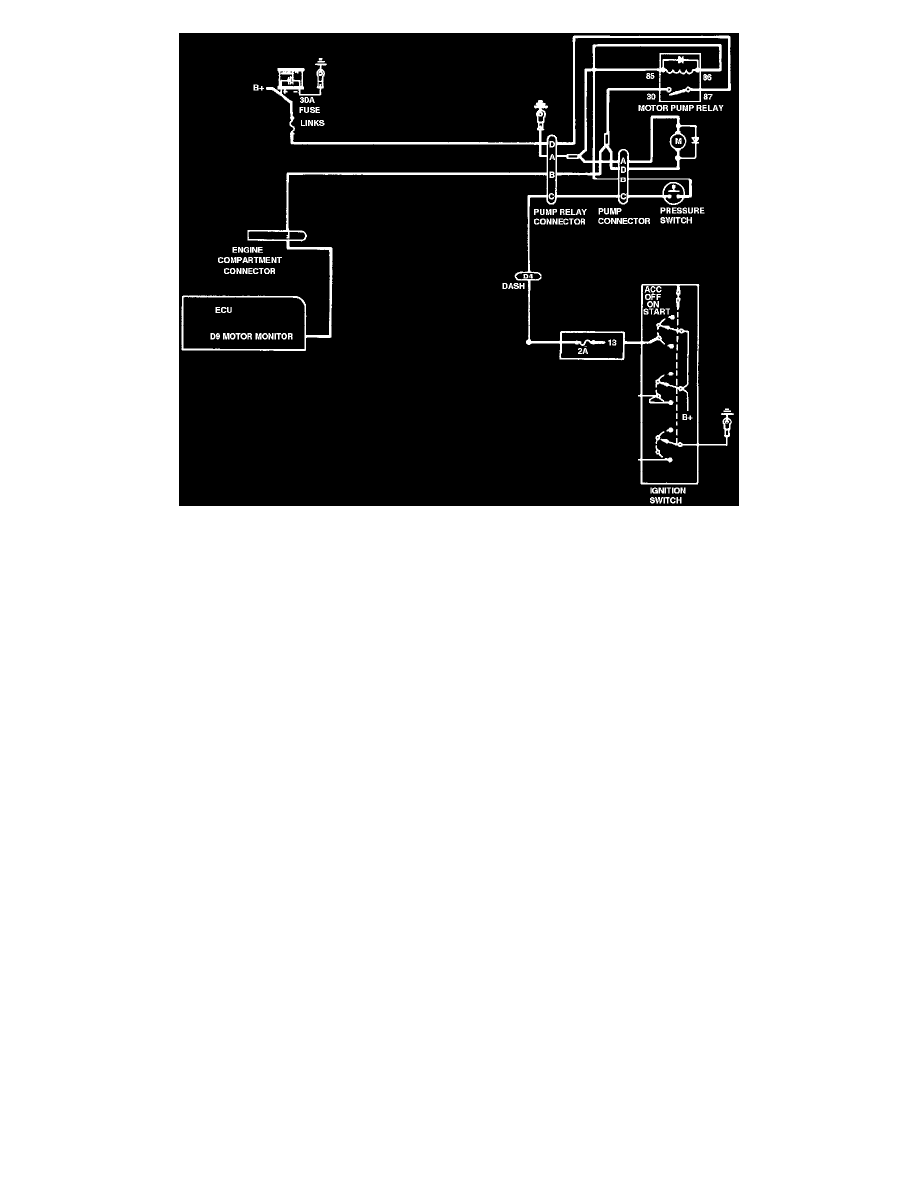
Fig. 20 Pump And Motor Circuitry
BOOSTER PUMP AND MOTOR ASSEMBLY
The booster pump and motor assembly is located under the hood on the passenger side of the vehicle. The booster pump is powered by an electric
motor, which is controlled through a relay by a pressure switch which is located next to the booster pump and motor assembly (fig. 18). The pump
piston operates off an eccentric drive. An internal relief valve and pressure switch control pump output. The pump and motor assembly are also
equipped with an accumulator to provide additional fluid supply for working pressure (fig. 19).
The pump supplies fluid boost pressure for both standard and anti-lock brake operation. Pump operating pressure range is approximately 1700-
2000 psi. The pressure switch closes when boost pressure drops below approximately 1700 psi. Battery voltage then goes to the motor through the
relay (fig. 20). When the pressure increases to approximately 2000 psi, the pressure switch will open, deenergizing the relay and the pump stops.
When the pressure switch closes, the anti-lock Electronic Control Unit (ECU) receives a signal to indicate that the motor has been energized. If the
pump remains energized for more than four minutes without the brakes being applied, the ECU will illuminate the red light on the instrument
panel. If the brake pressure in the pump exceeds approximately 3000 psi a pressure relief valve located in the pump will open allowing pressure to
drop inside the pump.
Finally, the pump motor is also equipped with a thermal fuse which shuts the pump off if operating temperature reaches about 385° F. The fuse
cannot be reset, the pump must be replaced if the fuse is blown.