
Wagoneer L6-242 4.0L VIN L FI (1989)
Throttle Position Sensor: Adjustments
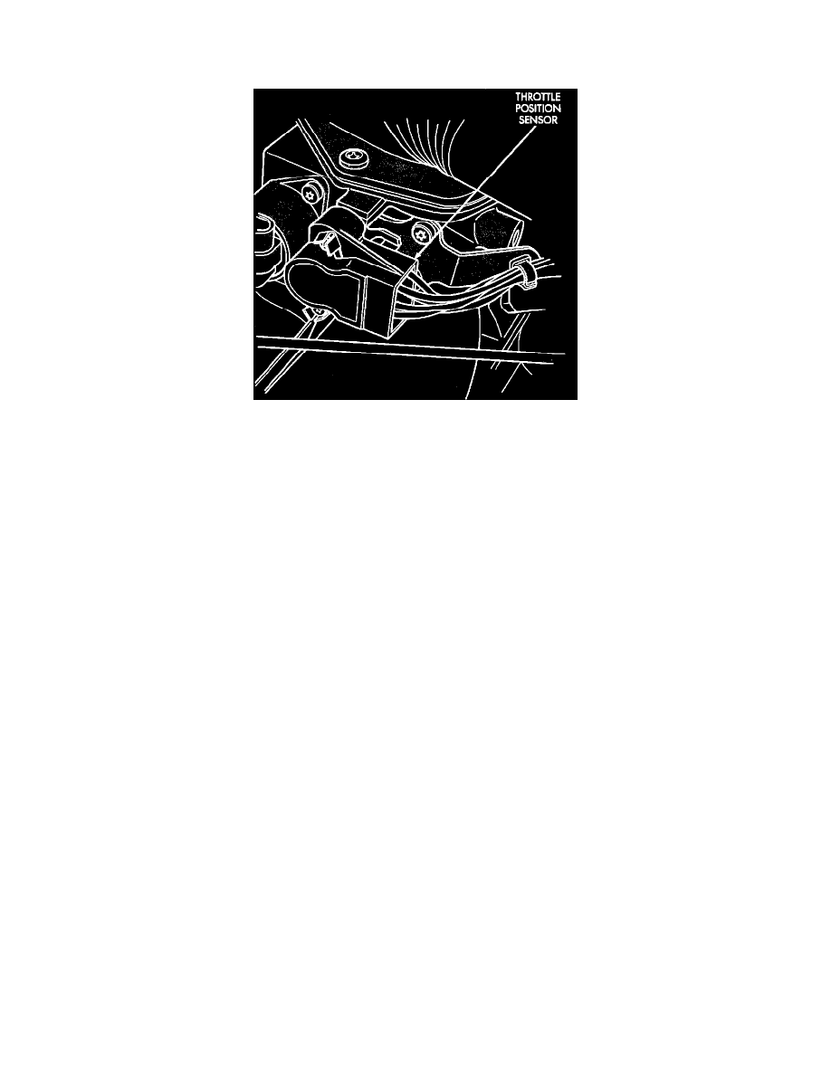
Automatic Transmission
Throttle Position Sensor (TPS) Location (Automatic Transmission)
NOTE: A digital voltmeter is required to successfully complete the adjustment of the TPS. The DRB II or an equivalent scan tool can also be
used to adjust the TPS. Refer to the scan tools' manual for adjustment procedure.
CAUTION:Do not disconnect the TPS electrical connector; instead, insert the voltmeter test leads into the back-side of the electrical connector.
When inserting the test leads, make sure that the wires and harnesses remain undamaged.
1.
Turn the ignition switch to the ON position.
2.
Find the Four-way TPS connector and insert the black lead of the voltmeter into the back side of terminal (D). Insert the red lead of the
voltmeter into the back side of terminal (A). Make sure that the throttle plate is completely closed against the throttle stop. Note the voltage
reading of the voltmeter as it is connected across these two terminals, this reading is the input voltage.
3.
Remove the red lead of the voltmeter from the back side of terminal (A) and reinstall it into the back side of terminal (B). Make sure that the
throttle plate is completely closed against the throttle stop. Note the voltage reading of the voltmeter as it is connected across terminals (B)
and (D), this reading is the output voltage.
4.
Divide the output voltage reading by the input voltage reading. The ratio should be between .825 and .835 (.830 optimum).
5.
If the voltage ratio is not within this range, adjustments can be made using the two mounting screws. To make large adjustments, loosen the
bottom mounting screw and pivot the sensor. To make small adjustments, loosen the top mounting screw and pivot the sensor.
6.
Disconnect the voltmeter, and tighten the mounting screws securely.