
Wrangler L6-4.0L VIN S (2000)
over the rod bolts will provide protection during removal.
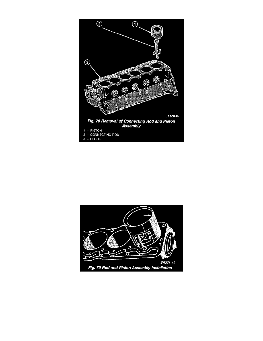
Fig. 78
12. Have an assistant push the piston and connecting rod assemblies up and through the top of the cylinder bores (Fig. 78).
INSTALLATION
1. Clean the cylinder bores thoroughly. Apply a light film of clean engine oil to the bores with a clean lint-free cloth.
2. Install the piston rings on the pistons if removed.
3. Lubricate the piston and rings with clean engine oil.
CAUTION: Ensure that connecting rod bolts DO NOT scratch the crankshaft journals or cylinder walls. Short pieces of rubber hose slipped over
the connecting rod bolts will provide protection during installation.
Fig. 79
4. Use a piston ring compressor to install the connecting rod and piston assemblies through the top of the cylinder bores (Fig. 79).
5. Ensure the arrow on the piston top points to the front of the engine (Fig. 79).
6. Raise the vehicle.
7. Each bearing insert is fitted to its respective journal to obtain the specified clearance between the bearing and the journal. In production, the select
fit is obtained by using various-sized, color-coded bearing inserts as listed in the Connecting Rod Bearing Fitting Chart. The color code appears on
the edge of the bearing insert. The size is not stamped on inserts used for production of engines.
8. The rod journal is identified during the engine production by a color-coded paint mark on the adjacent cheek or counterweight toward the flange
(rear) end of the crankshaft. The color codes used to indicate journal sizes are listed in the Connecting Rod Bearing Fitting Chart.
9. When required, upper and lower bearing inserts of different sizes may be used as a pair (refer to Connecting Rod Bearing Fitting Chart). A