
Wrangler L6-4.0L VIN S (2000)
Fuel Gauge Sender: Description and Operation
FUEL GAUGE SENDING UNIT
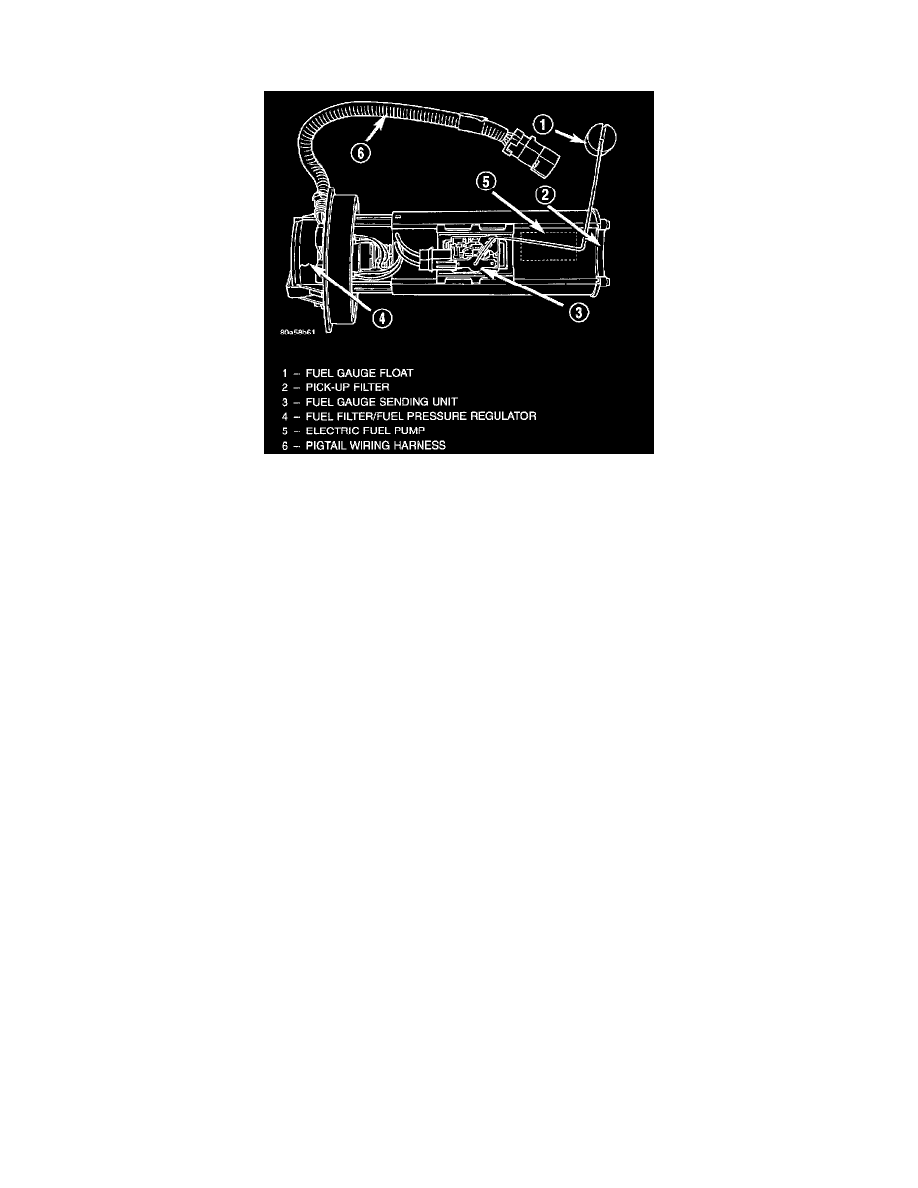
Fuel Pump Module Components
The fuel gauge sending unit (fuel level sensor) is attached to the side of the fuel pump module. The sending unit consists of a float, an arm, and a
variable resistor track (card).
The fuel pump module has 4 different circuits (wires). Two of these circuits are used for the fuel gauge sending unit for fuel gauge operation, and
for certain OBD II emission requirements. The other 2 wires are used for electric fuel pump operation.
Fuel Gauge Operation
A constant input voltage source of about 12 volts (battery voltage) is supplied to the resistor track on the fuel gauge sending unit. This is fed
directly from the Power train Control Module (PCM). NOTE: For diagnostic purposes, this 12 volt power source can only be verified with the
circuit opened (fuel pump module electrical connector unplugged). With the connectors plugged, output voltages will vary from about 0.6 volts at
FULL, to about 8.6 volts at EMPTY for Jeep models and about 7.0 volts at EMPTY for Dodge Truck models. The resistor track is used to vary
the voltage (resistance) depending on fuel tank float level. As fuel level increases, the float and arm move up, which decreases voltage. As fuel
level decreases, the float and arm move down, which increases voltage. The varied voltage signal is returned back to the PCM through the sensor
return circuit.
Both of the electrical circuits between the fuel gauge sending unit and the PCM are hard-wired (not multi-plexed). After the voltage signal is sent
from the resistor track, and back to the PCM, the PCM will interpret the resistance (voltage) data and send a message across the multi-plex bus
circuits to the instrument panel cluster. Here it is translated into the appropriate fuel gauge level reading. Refer to Instrument Panel for additional
information.
OBD II Emission Monitor Requirements
The PCM will monitor the voltage output sent from the resistor track on the sending unit to indicate fuel level. The purpose of this feature is to
prevent the OBD II system from recording/setting false misfire and fuel system monitor diagnostic trouble codes. The feature is activated if the
fuel level in the tank is less than approximately 15 percent of its rated capacity. If equipped with a Leak Detection Pump (EVAP system monitor),
this feature will also be activated if the fuel level in the tank is more than approximately 85 percent of its rated capacity.
FUEL LEVEL SENSOR - PCM INPUT
The fuel gauge level sending unit is attached to the fuel pump module.
The fuel level sensor (fuel gauge sending unit) sends a signal to the PCM to indicate fuel level. The purpose of this feature is to prevent a false
setting of misfire and fuel system monitor trouble codes if the fuel level is less than approximately 15 percent of its rated capacity. It is also used
to send a signal for fuel gauge operation via the PCI bus circuits.