
Wrangler L6-4.0L VIN S (2000)
Camber adjustment
If cross camber is greater than 0.5 deg., select the wheel furthest from the preferred value and replace that ball joint with the appropriate offset ball joint
listed above. The target value of the adjusted side must equal the unadjusted side, providing a cross camber value of 0.0 deg. Never compensate for drift
with additional cross caster. This could compromise vehicle handling.
NOTE:
WHENEVER CHANGING THE SETTING ON THE BALL JOINT FOR ALIGNMENT, THE ALIGNER HEADS MUST BE
RE-COMPENSATED. ERRORS WILL RESULT IF THIS IS NOT DONE.
Caster Adjustment:
It cross caster is greater than the specifications shown above, utilize the offset ball joint to reduce the cross caster. If individual caster is above the
specifications, utilize the cam or shim adjustment where possible. Use the offset ball joints if the caster cannot be adjusted using the other methods.
Target caster is shown above if two offset ball joints are used. Offset ball joints will not effect drive line (propeller shaft) angles. If caster angles are
changed using shims or cams, always road test the vehicle to verify that no drive line disturbance has been created. Verify steering wheel is centered.
Never compensate for drift with additional cross caster. This could compromise vehicle handling.
Ball Joint Installation:
1.
Remove the wheel, and tire assemblies.
2.
Remove the brake caliper and rotor.
3.
Remove the tie rod from the knuckle.
4.
Remove the hub, bearing, axle shaft and nut.
5.
Remove the nuts from the upper and lower ball joints.
6.
Strike the steering knuckle with a brass hammer to loosen the knuckle from the ball joint. Lower the knuckle from the studs.
7.
Using the ball joint removal tool Number 4142F, remove the upper ball joint.
B.
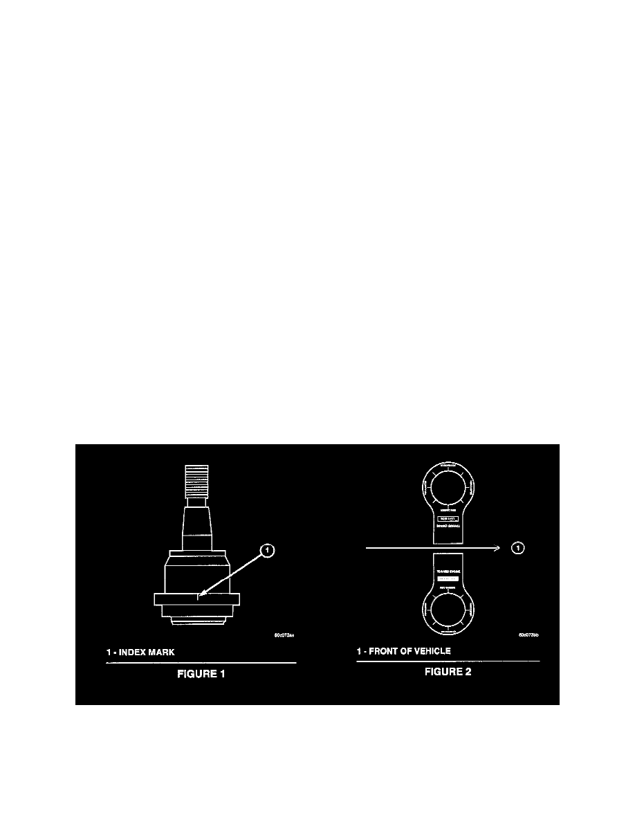
Position the template supplied in the ball joint package on the top of the axle yoke.
9.
Position the offset ball joint in the appropriate position using the reference mark located on the largest diameter on side of the ball stud with the
desired change mark on the template (see Figure 1 & Figure 2)
10.
Using the installation tool, number 4142F, and the installation sleeve provided in the package, press the ball joint half way into the bore. Remove
the template and press the ball joint the remainder of the way into the bore until fully seated.
11.
Install the dust boot and grease fitting provided.