
Wrangler 2WD V6-3.8L (2008)
Antenna, Radio: Testing and Inspection
ANTENNA BODY AND CABLE
WARNING: On vehicles equipped with airbags, refer to Restraint Systems / Service Precautions, before attempting any steering wheel,
steering column, or instrument panel component diagnosis or service. Failure to take the proper precautions could result in accidental airbag
deployment and possible personal injury.
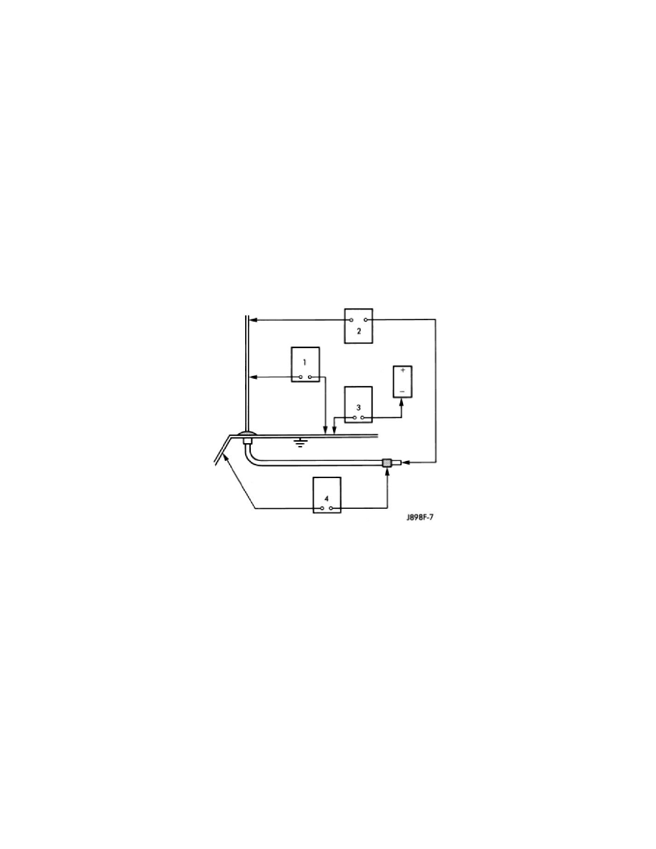
The following four tests are used to diagnose the antenna with an ohmmeter:
-
Test 1 - Mast to ground test
-
Test 2 - Tip-of-mast to tip-of-conductor test
-
Test 3 - Body ground to battery ground test
-
Test 4 - Body ground to coaxial shield test.
The ohmmeter test lead connections for each test are shown in Antenna Tests.
NOTE: This model has a two-piece antenna coaxial cable. Tests 2 and 4 must be conducted in two steps to isolate an antenna cable problem.
First, test the primary antenna cable (integral to the antenna body and cable) from the coaxial cable connector behind the right side of the
instrument panel between the radio and the right side cowl panel, to the antenna body. Then, test the secondary antenna cable (instrument
panel antenna cable) from the coaxial connector behind the right side of the instrument panel between the radio and the right side cowl panel,
to the coaxial cable connector at the radio.
TEST 1
Test 1 determines if the antenna mast is insulated from the base. Proceed as follows:
1. Unplug the antenna coaxial cable connector from the radio chassis and isolate.
2. Connect one ohmmeter test lead to the tip of the antenna mast. Connect the other test lead to the antenna base. Check for continuity.
3. There should be no continuity. If continuity is found, replace the faulty or damaged antenna base and cable assembly.
TEST 2
Test 2 checks the antenna for an open circuit as follows:
1. Unplug the antenna coaxial cable connector from the radio chassis.
2. Connect one ohmmeter test lead to the tip of the antenna mast. Connect the other test lead to the center pin of the antenna coaxial cable connector.
3. Continuity should exist (the ohmmeter should only register a fraction of an ohm). High or infinite resistance indicates damage to the base and cable
assembly. Replace the faulty base and cable, if required.
TEST 3
Test 3 checks the condition of the vehicle body ground connection. This test should be performed with the battery positive cable removed from the
battery. Disconnect both battery cables, the negative cable first. Reconnect the battery negative cable and perform the test as follows:
1. Connect one ohmmeter test lead to the vehicle fender. Connect the other test lead to the battery negative post.