
Wrangler 4WD L4-150 2.5L VIN P MFI (1998)
Hydraulic Control Assembly - Antilock Brakes: Description and Operation
Hydraulic Control Unit (HCU)
HYDRAULIC CONTROL UNIT
Hydraulic Control Unit
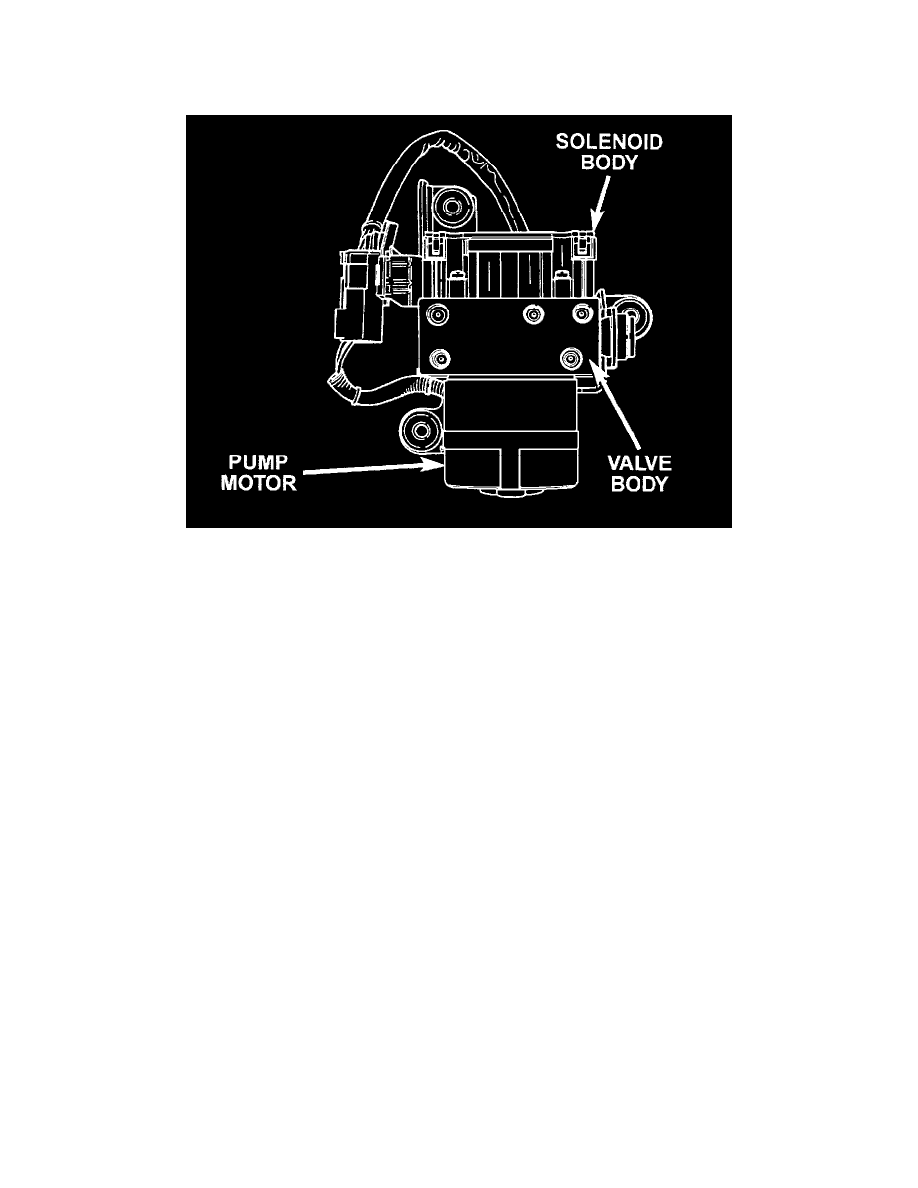
The Hydraulic Control Unit (HCU) consists of a valve body, pump body, accumulators, pump motor, and wire harnesses.
The pump, motor, and accumulators are combined into an assembly attached to the valve body. The accumulators store the extra fluid released to the
system for ABS mode operation. The pump provides the fluid volume needed and is operated by a DC type motor. The motor is controlled by the
CAB.
The valve body contains the solenoid valves. The valves modulate brake pressure during antilock braking and are controlled by the CAB.
The HCU provides three channel pressure control to the front and rear brakes. One channel controls the rear wheel brakes in tandem. The two
remaining channels control the front wheel brakes individually.
During antilock braking, the solenoid valves are opened and closed as needed. The valves are not static. They are cycled rapidly and continuously to
modulate pressure and control wheel slip and deceleration.
During normal braking, the HCU solenoid valves and pump are not activated. The master cylinder and power booster operate the same as a vehicle
without an ABS brake system.
During antilock braking, solenoid valve pressure modulation occurs in three stages, pressure increase, pressure hold, and pressure decrease. The
valves are all contained in the valve body portion of the HCU.
Pressure Decrease
The outlet valve is opened and the inlet valve is closed during the pressure decrease cycle.
A pressure decrease cycle is initiated when speed sensor signals indicate high wheel slip at one or more wheels. At this point, the CAB closes the inlet
then opens the outlet valve, which also opens the return circuit to the accumulators. Fluid pressure is allowed to bleed off (decrease) as needed to
prevent wheel lock.
Once the period of high wheel slip has ended, the CAB closes the outlet valve and begins a pressure increase or hold cycle as needed.
Pressure Hold
Both solenoid valves are closed in the pressure hold cycle. Fluid apply pressure in the control channel is maintained at a constant rate. The CAB