
Wrangler 4WD L4-150 2.5L VIN P MFI (1998)
Control Assembly: Service and Repair
WARNING: ON VEHICLES EQUIPPED WITH AIRBAGS, REFER TO AIRBAGS BEFORE ATTEMPTING ANY STEERING WHEEL,
STEERING COLUMN, OR INSTRUMENT PANEL COMPONENT DIAGNOSIS OR SERVICE. FAILURE TO TAKE THE PROPER
PRECAUTIONS COULD RESULT IN ACCIDENTAL AIRBAG DEPLOYMENT AND POSSIBLE PERSONAL INJURY.
REMOVAL
1. Disconnect and isolate the battery negative cable.
2. Remove the glove box from the instrument panel.
3. Remove the center bezel from the instrument panel. Refer to Instrument Panel Center Bezel in Instrument Panel, Gauges and Warning
Indicators/Instrument Panel Systems for the procedures.
4. Reach through the glove box opening to unplug the two halves of the vacuum harness connector.
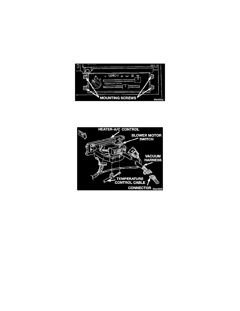
Heater-A/C Control Remove/Install
5. Remove the four screws that secure the heater-A/C control to the instrument panel.
6. Pull the heater-A/C control assembly away from the instrument panel far enough to access the connections on the back of the control.
Heater-A/C Control Connections
7. Unplug the three wire harness connectors from the back of the heater-A/C control.
8. Release the temperature control cable housing flag retainer latch in the receptacle on the back of the heater-A/C control and disengage the flag
retainer from the receptacle.
9. Disengage the temperature control cable end from the pin of the temperature control lever on the back of the heater-A/C control.
10. Remove the heater-A/C control from the instrument panel.
INSTALLATION
1. Connect the temperature control cable end to the pin of the temperature control lever on the back of the heater-A/C control.
2. Connect the temperature control cable housing flag retainer to the receptacle on the back of the heater-A/C control.
3. Plug the three wire harness connectors into the back of the heater-A/C control.
4. Position the heater-A/C control in the instrument panel and secure it with four screws. Tighten the screws to 2.2 N.m (20 in. lbs.).
5. Reach through the glove box opening to plug the two halves of the vacuum harness connector back together.
6. Reinstall the glove box in the instrument panel. Refer to Glove Box in Instrument Panel Systems for the procedures.
7. Reinstall the instrument panel center bezel onto the instrument panel. Refer to Instrument Panel Center Bezel in Instrument Panel, Gauges and
Warning Indicators/Instrument Panel Systems for the procedures. See: Instrument Panel, Gauges and Warning Indicators/Instrument Cluster /
Carrier/Service and Repair
8. Connect the battery negative cable.