
Wrangler 4WD L4-150 2.5L VIN P MFI (1998)
Data Link Connector: Description and Operation
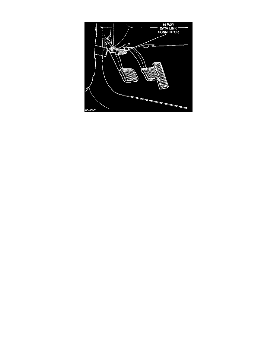
Fig. 10 Data Link Connector Location
DATA LINK CONNECTOR-PCM INPUT AND OUTPUT
The 16-way data link connector (diagnostic scan tool connector) links the Diagnostic Readout Box (DRB) scan tool or the Mopar Diagnostic
System (MDS) with the powertrain control module (PCM). The data link connector is located under the instrument panel to the left of the steering
column (Fig. 10). For operation of the DRB scan tool, refer to the appropriate Powertrain Diagnostic/Computers and Control/Testing and
Inspection Procedures.
CIRCUIT OPERATION
Circuit M1 from the Ignition Off Draw (IOD) fuse in cavity 17 of the Power Distribution Center (PDC) supplies battery voltage to the data link
connector.
Circuit D20 connects to cavity C29 of the PCM. Circuit D20 is the SCI receive circuit for the Powertrain Control Module (PCM). Circuit D21
connects to cavity C27 of the PCM and cavity A3 of the Controller, Anti Lock Brakes (CAB). Circuit D21 is the SCI transmit circuit for the PCM
CCD Bus Circuits D1 and D2 connect to the data link connector.
Circuit Z12 provide ground for the data link connector. Circuit Z12 also connects to cavities A31 and A32 of the PCM.