
Wrangler 4WD L4-150 2.5L VIN P MFI (1998)
Power Steering Pump Pressure Switch
POWER STEERING PRESSURE SWITCH-PCM INPUT
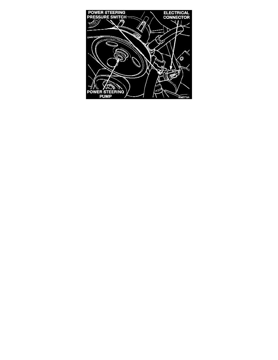
A pressure sensing switch is included in the power steering system (mounted on the high-pressure line). This switch will be on vehicles equipped
with power steering. The switch (Fig. 9) provides an input to the Powertrain Control Module (PCM). This input is provided during periods of high
pump load and low engine rpm; such as during parking maneuvers. The PCM will then increase the idle speed through the Idle Air Control (IAC)
motor. This is done to prevent the engine from stalling under the increased load.
When steering pump pressure exceeds 3275 kPa +/- 690 kPa (475 psi +/- 100 psi), the normally closed switch will open and the PCM will
increase the engine idle speed. This will prevent the engine from stalling.
When steering pump pressure drops below approximately 1379 kPa (200 psi), the switch circuit will close and engine idle speed will return to its
previous setting.
CIRCUIT OPERATION
The Powertrain Control Module (PCM) connects to the power steering pressure switch on circuit K10. Circuit K10 connects to cavity A12 of the
PCM. Circuit Z1 provides ground for the switch. When the switch closes, it connects circuit K10 to ground. The switch closes during periods of
high power steering pump load and low engine speed; such as parking maneuvers
Sensor Return-PCM Input
Sensor Return provides a low noise ground reference for all engine control system sensors.
Signal Ground-PCM Input
Signal ground provides a low noise ground to the data link connector.
Speed Control Solenoids-PCM Output
Speed control operation is regulated by the powertrain control module (PCM). The PCM controls the vacuum to the throttle actuator through the speed
control vacuum and vent solenoids.
Speed Control Switches-PCM Input
Two separate speed control switch modules are mounted on the steering wheel to the left and right side of the driver's airbag module. Within the two
switch modules, five momentary contact switches, supporting seven different speed control functions are used. The outputs from these switches are
filtered into one input. The Powertrain Control Module (PCM) determines which output has been applied through resistive multiplexing. The input
circuit voltage is measured by the PCM to determine which switch function has been selected.
A speed control indicator lamp, located on the instrument panel cluster is energized by the PCM via the CCD Bus. This occurs when speed control
system power has been turned ON, and the engine is running.
The two switch modules are labeled: ON/OFF, SET, RESUME/ACCEL, CANCEL and COAST.
Tachometer-PCM Output
TACHOMETER-PCM OUTPUT
The Powertrain Control Module (PCM) supplies engine rpm values to the instrument cluster tachometer through the PCM's CCD (Information)
bus circuits. Refer Instrument Panel and Gauges for tachometer information.