
Wrangler 4WD L4-150 2.5L VIN P MFI (1998)
SYSTEM OPERATION
The tachometer gives an indication of the engine speed in revolutions-per-minute (rpm). The instrument cluster circuitry controls the gauge
pointer position. The instrument cluster circuitry calculates the proper gauge pointer position based upon an engine speed message received from
the Powertrain Control Module (PCM) on the Chrysler Collision Detection (CCD) data bus.
The PCM uses an input from the crankshaft position sensor and internal programming to calculate what engine speed message is required. The
PCM then sends the proper message to the instrument cluster on the CCD data bus.
The crankshaft position sensor is installed near the rear of the engine, where it is aimed at the trigger wheel attached to the rear flange of the
crankshaft.
CIRCUIT OPERATION
The Powertrain Control Module (PCM) broadcasts the engine RPM data on the CCD bus. From the RPM message on the CCD bus, the instrument
cluster calculates tachometer needle position.
Throttle Position Sensor (TPS)-PCM Input
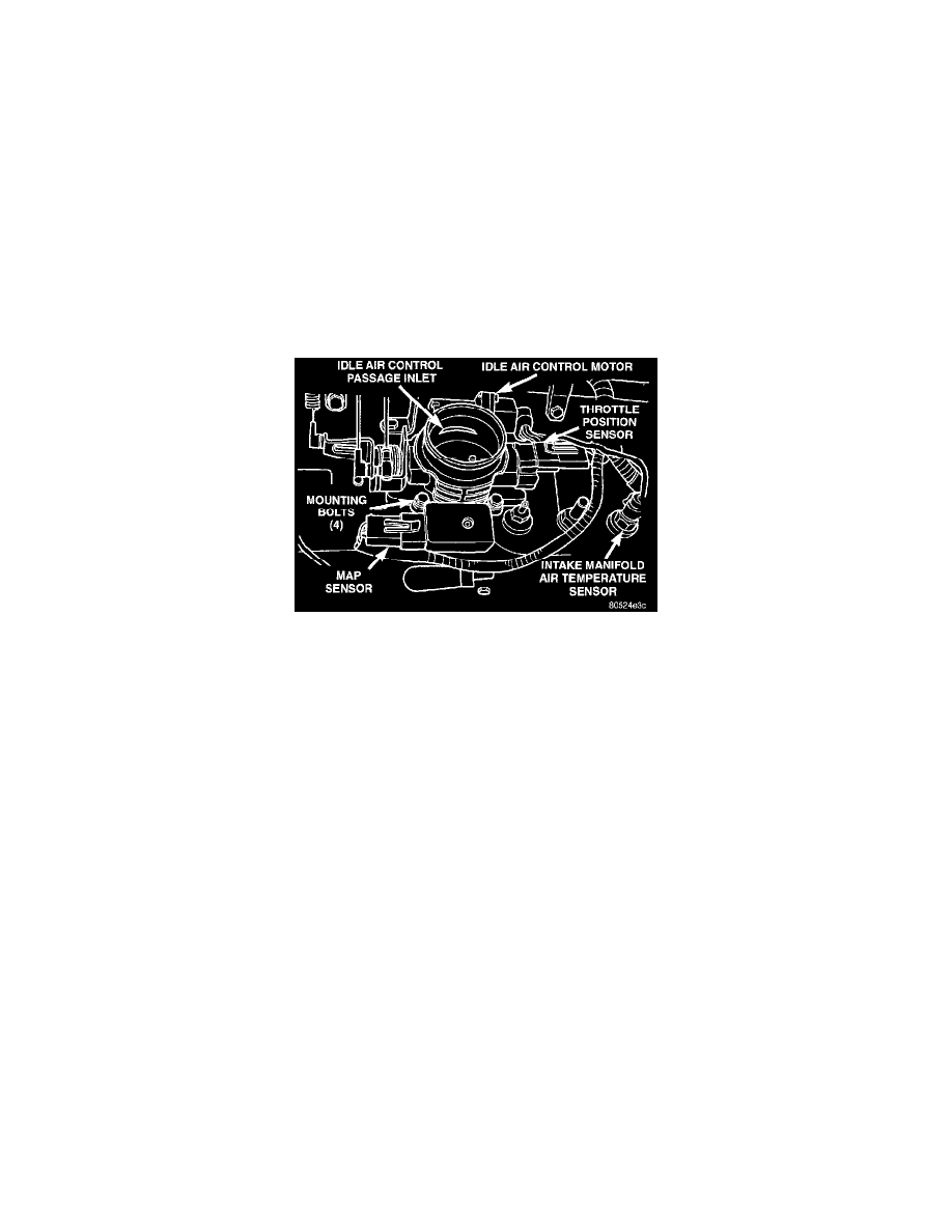
Fig. 7 Intake Air Temp. Sensor Location-Typical
THROTTLE POSITION SENSOR (TPS)-PCM INPUT
The Throttle Position Sensor (TPS) is mounted on the throttle body (Fig. 7). The TPS is a variable resistor that provides the Powertrain Control
Module (PCM) with an input signal (voltage) that represents throttle blade position. The sensor is connected to the throttle blade shaft. As the
position of the throttle blade changes, the resistance of the TPS changes.
The PCM supplies approximately 5 volts to the TPS. The TPS output voltage (input signal to the PCM) represents the throttle blade position. The
PCM receives an input signal voltage from the TPS. This will vary in an approximate range of from 1 volt at minimum throttle opening (idle), to 4
volts at wide open throttle. Along with inputs from other sensors, the PCM uses the TPS input to determine current engine operating conditions. In
response to engine operating conditions, the PCM will adjust fuel injector pulse width and ignition timing.
CIRCUIT OPERATION
From the Powertrain Control Module (PCM), circuit K7 supplies 5 Volts to the throttle position sensor (TPS) Circuit K7 connects to cavity A17
of the PCM.
Circuit K22 delivers the TPS signal to the PCM Circuit K22 connects to cavity A23 of the PCM.
The PCM provides a ground for the throttle position sensor signal (circuit K22) through circuit K167 Circuit K167 connects to cavity A4 of the
PCM.
Transmission Park/Neutral Switch-PCM Input
TRANSMISSION PARK/NEUTRAL SWITCH-PCM INPUT
The park/neutral switch is located on the transmission housing and provides an input to the Powertrain Control Module (PCM). This will indicate
that the automatic transmission is in Park, Neutral or a drive gear selection. This input is used to determine idle speed (varying with gear
selection), fuel injector pulse width and ignition timing advance. Refer to Transmissions, for testing, replacement and adjustment information.
Vehicle Speed and Distance Sensor-PCM Input