
Wrangler 4WD L4-150 2.5L VIN P MFI (1998)
-
Right Turn signal
-
Master Illumination (export only)
LAMPS (CCD)
The following lamps are controlled by the cluster via CCD messages. They are actuated during the self-test procedure.
-
Low Fuel Warning
-
Airbag
-
Seat Belt
-
Upshift (if equipped)
-
Check Engine
-
Check Gauges
Crankshaft Position Sensor-PCM Input
CRANKSHAFT POSITION SENSOR-PCM INPUT
This sensor is a hall effect device that detects notches in the flywheel (manual transmission) or flexplate (automatic transmission).
This sensor is used to indicate to the Powertrain Control Module (PCM) that a spark and or fuel injection event is to be required. The output from
this sensor, in conjunction with the camshaft position sensor signal, is used to differentiate between fuel injection and spark events. It is also used
to synchronize the fuel injectors with their respective cylinders.
The sensor is bolted to the transmission bellhousing.
Refer to Ignition System for more crankshaft position sensor information.
NOTE: The engine will not operate if the PCM does not receive a crankshaft position sensor input.
Data Link Connector-PCM Input and Output
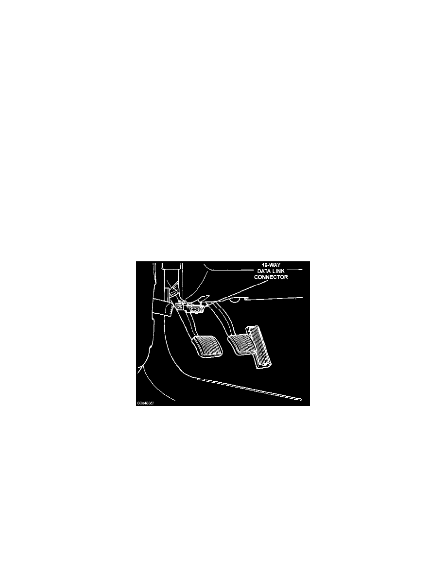
Fig. 10 Data Link Connector Location
DATA LINK CONNECTOR-PCM INPUT AND OUTPUT
The 16-way data link connector (diagnostic scan tool connector) links the Diagnostic Readout Box (DRB) scan tool or the Mopar Diagnostic
System (MDS) with the powertrain control module (PCM). The data link connector is located under the instrument panel to the left of the steering
column (Fig. 10). For operation of the DRB scan tool, refer to the appropriate Powertrain Diagnostic/Computers and Control/Testing and
Inspection Procedures.
CIRCUIT OPERATION
Circuit M1 from the Ignition Off Draw (IOD) fuse in cavity 17 of the Power Distribution Center (PDC) supplies battery voltage to the data link
connector.
Circuit D20 connects to cavity C29 of the PCM. Circuit D20 is the SCI receive circuit for the Powertrain Control Module (PCM). Circuit D21
connects to cavity C27 of the PCM and cavity A3 of the Controller, Anti Lock Brakes (CAB). Circuit D21 is the SCI transmit circuit for the PCM
CCD Bus Circuits D1 and D2 connect to the data link connector.
Circuit Z12 provide ground for the data link connector. Circuit Z12 also connects to cavities A31 and A32 of the PCM.