
Amanti V6-3.5L (2006)
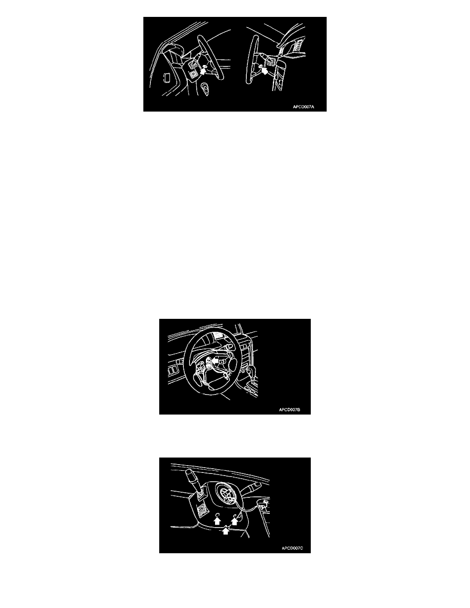
2. Remove the airbag module.
WARNING: The SRS is designed to retain enough power to deploy the air bag for about 30 seconds even after the battery has been
disconnected, so serious injury may result from unintended air bag deployment if service is done on the SRS immediately after the battery
cable is disconnected.
-
Never attempt to disassemble or repair the air bag module or clock spring. If faulty, replace it.
-
Do not drop the air bag module or clock spring or allow contact with water, grease or oil. Replace if a dent, crack, deformation or rust is
detected.
-
The air bag module should be stored on a flat surface and placed so that the pad surface is facing upward. Do not place anything on top of it.
-
Do not expose the air bag module to temperatures over 93 °C (200 °F).
-
After deployment of an air bag, replace the clock spring with a new one.
-
Wear gloves and safety glasses when handing an air bag that has been deployed.
-
An undeployed air bag module should only be disposed of in accordance with the procedures mentioned in the restraints section.
-
When you disconnect the air bag module-clock spring connector, take care not to apply excessive force.
-
The removed air bag module should be stored in a clean, dry place.
-
Prior to installing the clock spring, align the mating mark and "NEUTRAL" position indicator of the clock spring, and after turning the front
wheels to the straight-ahead position, install the clock spring to the column switch. If the mating mark of the clock spring is not properly
aligned, the steering wheel may not completely rotate during a turn, or the flat cable within the clock spring may be broken obstructing normal
operation of the SRS and possibly leading to serious injury to the vehicle's driver. To inspect the clock spring, refer to the restraints section.
3. Remove the steering wheel lock nut and washer.
4. Mark the steering column shaft and steering wheel for fitting positions used for re-installation using the special tool. Remove the steering wheel.
NOTE: Do not use a hammer on the steering wheel to remove it.
5. Remove the steering column lower and upper shroud.