
Amanti V6-3.8L (2007)
Function
^
Between two electrically charged stationary plates having the same polarity, an electrically charged silicon element having the opposite polarity is
attached to the end of a cantilever arm.
^
Between these three plates, two electric fields are generated by the capacitances C1 and C2.
^
The capacitances C1 and C2 change in response to lateral acceleration. This change can be used to calculate the direction and amount of lateral
acceleration acting on the vehicle.
^
The same sensor can also be used as longitudinal acceleration sensor if it is installed in the direction of travel (e.g. VW 4 motion with Haldex
clutch).
^
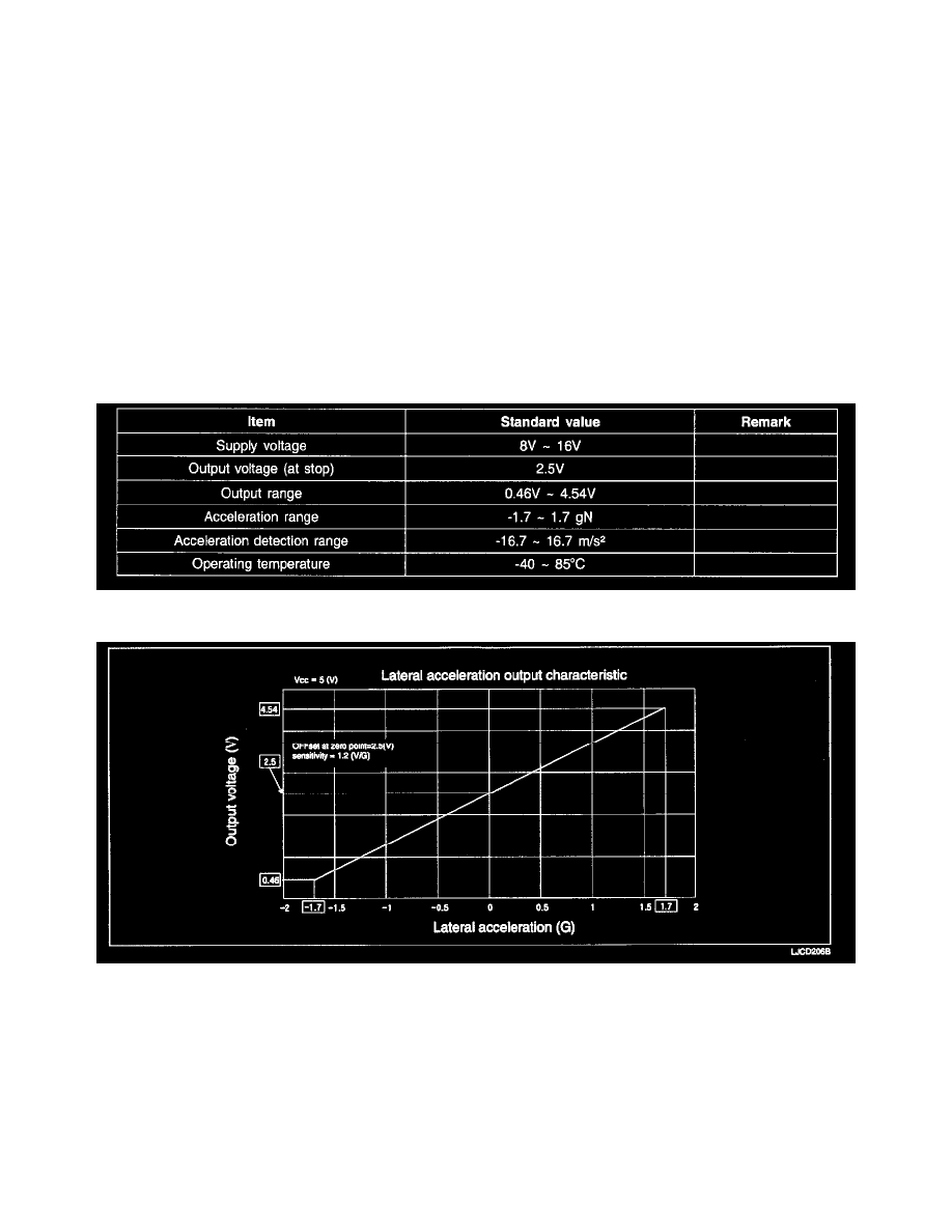
For 0 g lateral acceleration, the sensor produces an output signal with a voltage of 2.5 V
Other
^
The signal of the lateral acceleration sensor alone cannot trigger an ESC intervention. The sensor is mainly used for estimating the coefficient of
friction.
^
The installation location of the lateral acceleration sensor is more critical than that of the yaw-rate sensor (lever arm).
^
The installation location may not be changed after repairs.
1. Specification
2. Output voltage
3. Circuit Diagram