
Amanti V6-3.8L (2007)
Voltage in these circuits should be tested only with a 10-megaohm or higher impedance DVOM. Never use a test lamp on circuits that contain solid state
modules. Damage to the modules may result.
A voltmeter can be used in place of a test lamp. While a test lamp shows whether the voltage is present or not, a voltmeter indicates how much voltage is
present.
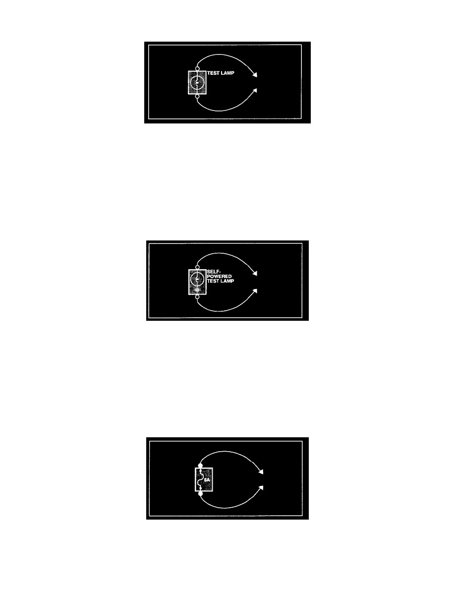
SELF-POWERED TEST LAMP AND OHMMETER
Use a self-powered test lamp or an ohmmeter to check for continuity. The ohmmeter shows how much resistance there is between two points along a
circuit. Low resistance means good continuity.
CAUTION Never use a self-powered test lamp on circuits that contain solid state modules. Damage to these modules may result.
An ohmmeter can be used in place of a self-powered test lamp.
The ohmmeter shows how much resistance there is between two points along a circuit. Low resistance means good continuity.
Circuits which include any solid-state devices should be tested only with a 10-megaohm or higher impedance digital multimeter. When measuring
resistance with a digital multimeter, the component being tested should be isolated from the circuit (component disconnected, power OFF). Otherwise,
there may be incorrect readings. Diodes and solid-state devices in a circuit can make an ohmmeter give a false reading
To find out if a component is affecting a measurement, take one reading, reverse the leads and take a second reading.
If different the solid-state device is affecting the measurement.
JUMPER WIRE WITH FUSE
Use a jumper wire with a fuse to by-pass an open circuit.
A jumper wire is made up of an in-line fuse holder connected to a set of test leads. This tool is available with small clamp connectors providing adaption
to most connectors without damage.
CAUTION Do not use a fuse with a higher rating than the specified fuse that protects the circuit being tested. Do not use this tool in any
situation to substitute an input or output at the solid-state control module, such as ECM, TCM, etc.
SHORT FINDER