
Amanti V6-3.8L (2007)
In this case the measured resistance between connector (C) and (B1) is higher than 1 Mohm and the open circuit is between terminal 1 of
connector (C) and terminal 1 of connector (B1).
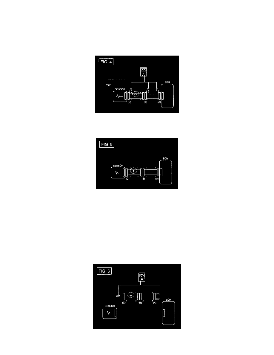
3. Voltage Check Method
a. With each connector still connected, measure the voltage between the chassis ground and terminal 1 of each connectors (A), (B) and (C) as
shown in [FIG. 4].
The measured voltage of each connector is 5 V, 5 V and 0 V respectively. So the open circuit is between connector (C) and (B).
CHECK SHORT CIRCUIT
4. Test Method for Short to Ground Circuit
-
Continuity Check with Chassis Ground
If short to ground circuit occurs as shown in [FIG. 5], the broken point can be found by performing below Step 2 (Continuity Check Method with
Chassis Ground) as shown below.
5. Continuity Check Method (with Chassis Ground)
NOTE: Lightly shake the wire harness above and below, or from side to side when measuring the resistance.
Specification (Resistance)
1 ohm or less -> Short to Ground Circuit
1 Mohm or Higher -> Normal Circuit
a. Disconnect connectors (A), (C) and measure for resistance between connector (A) and Chassis Ground as shown in [FIG. 6].