
Borrego 2WD V6-3.8L (2009)
Body Control Module: Description and Operation
Description
1 of 3
Operation
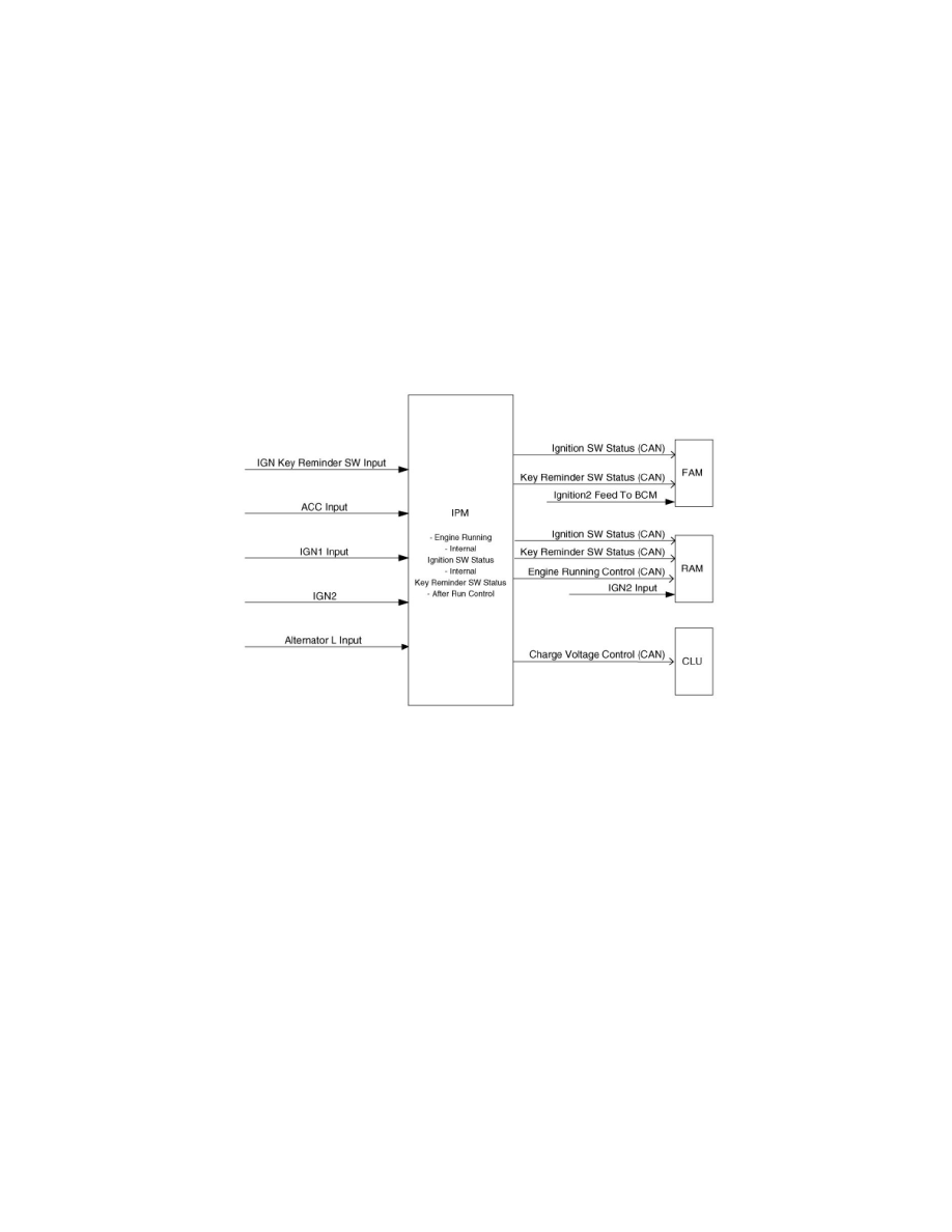
Engine and Ignition Key Control
Description
This function managed by the IPM, controls :
-
Ignition key position in the key cylinder (off, acc, run , start)
-
Ignition key reminder status (inserted or not)
-
Engine running status
-
Charging voltage
The data are transmitted on the CAN.
Functional Diagram
Exterior Lighting
Light MF switch (Multi - Function Light switch)
Description
The MF Light switch is used to manage the park lamps, the tail lamps and the headlamps low beam.
The park lamps, the tail lamps and the headlamps low beam status are determined by:
-
The light MF switch:
1) The MF light switch has 4 positions: OFF, Park and Tail, Headlamps Low Beam, Auto light.
2) It is connected to the IPM with 3 wires: Park and Tail lamp Sw, Headlamp Sw, Auto light Sw.
-
The Auto light function
-
The Escort function
-
The Battery Saver function
The Auto light function is active when the MF Light sw is in Auto light position and depends on the ignition key position. Based on the Auto light sensor
values corresponding to the exterior brightness level, it automatically manages the lighting of the park lamps, the tail lamps and the headlamps low beam.
Depending on the country, these lamps are controlled either separately or together.
The IPM manages the control logic of the functions, and sends the command to the RAM and the FAM that drive the lamps.
The FAM drives the turn signal park lamps and the side marker lamps. All these lamps are controlled simultaneously. The FAM also drives the
headlamps low beam and the HLLD, both in same time.
The RAM drives the tail lamps. Moreover, when the tail lamps are switched on, the license plate lamps are also lighted on.
The interior backlighting (IP backlight, switch illuminations) is managed with the same control logic as the park and tail lamps.
There is no indicator on the cluster for the park lamps, the tail lamps or the headlamps low beam.
For each of the park lamps, the tail lamps and the headlamps low beam, a status message is sent by FAM or RAM to the IPM and to CLU to indicate if
one lamp is in error.
Functional Diagram