
Borrego 4WD V6-3.8L (2009)
The hardware safe mode consists in maintaining the state of the low beam if the exterior lighting was active before entering the safe mode.
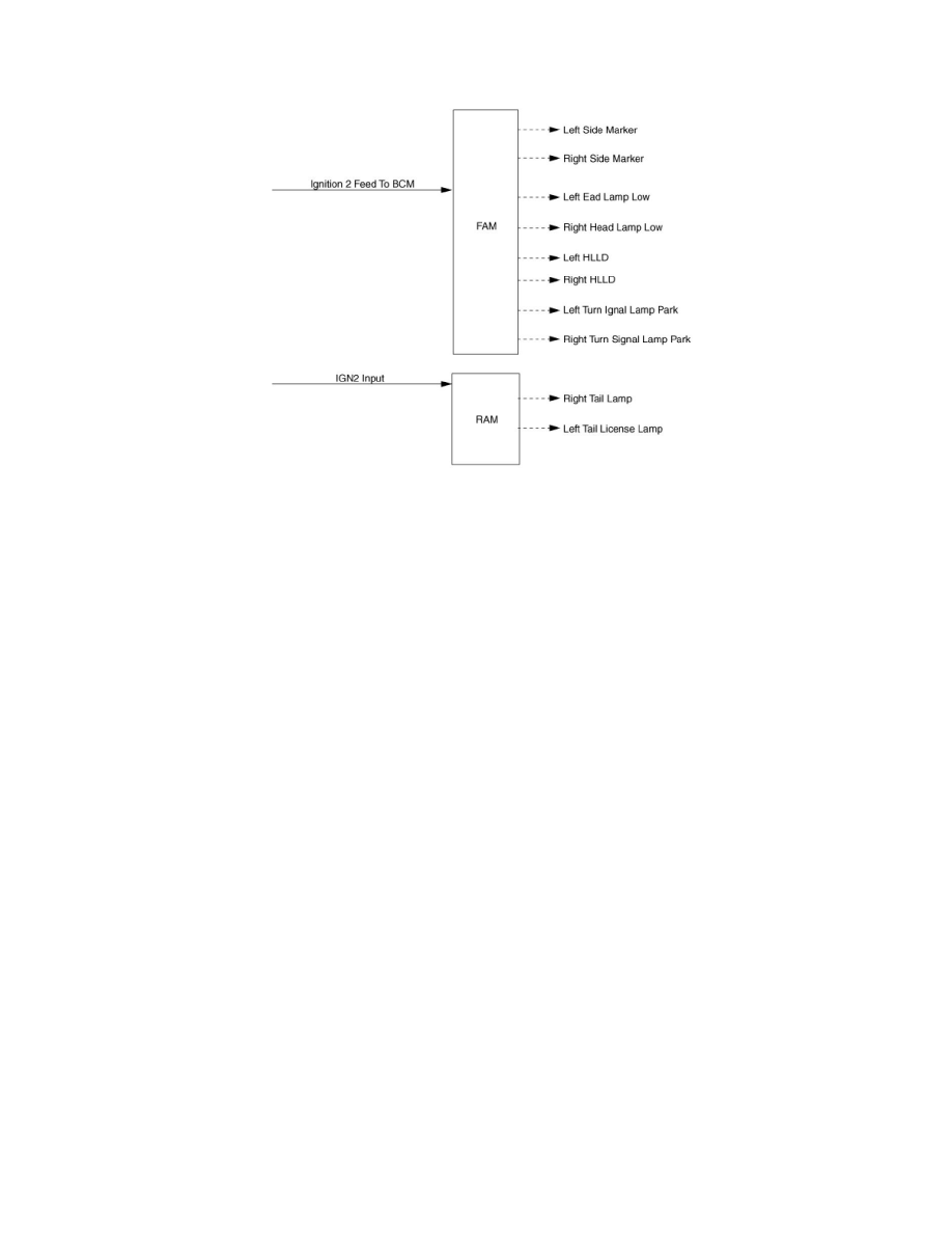
Functional Diagram
Rescue mode
Description
The goal of this mode is to be able to cope with failures that may happen on some of the most critical functionalities (for the driver security) of the
system.
There are 2 rescue modes:
-
The hardware rescue mode;
-
The software rescue mode.
The software rescue mode consists in activating some safety functions when IGN2_INPUT = ON:
Switch on the low beams (FAM), park lamps (FAM), tail lamps (RAM) and cluster backlighting (IPM);
Unlock of all the doors when the rescue mode is entered with IGN2_INPUT = ON
All other functions (apart from head lamp low beams, tail lamps and front wipers) will try to behave as specified and will enter their own default mode if
it is not possible.
Front wipers do not need to be turned on by software in rescue mode because wipers can be turned on by manually setting the MF switch to low speed.
The FAM software must keep the same state as before entering the rescue mode.
When IGN2_INPUT = OFF, low beams, park/tail lamps and cluster backlighting are turned off.
The hardware rescue mode will switch on the low beams and the tail lamps. The front wipers are not taken into account due to the direct wiring of the
stalk switch (low speed position).
The boards are designed to allow this hardware rescue mode to ensure their own integrity.
Note that none of the modules powered by IPM, RAM or FAM are kept powered in rescue mode.
Functional Diagram