
Borrego 4WD V6-3.8L (2009)
Turn Signal and Side Repeater Lamps
FAM
Description
The turn signal lamps status is determined by:
-
The left and right turn signal switches
-
The hazard switch
-
The crash unlock activation
-
The RKE lock, unlock, tailgate unlock and panic signals
-
The alarm activation
A sound relay connected to the Cluster manages the "tick" sound during the turn signal lamps activation.
The cluster has two backlight indicators: one for the left Turn Signal lamps and one for the right Turn Signal lamps.
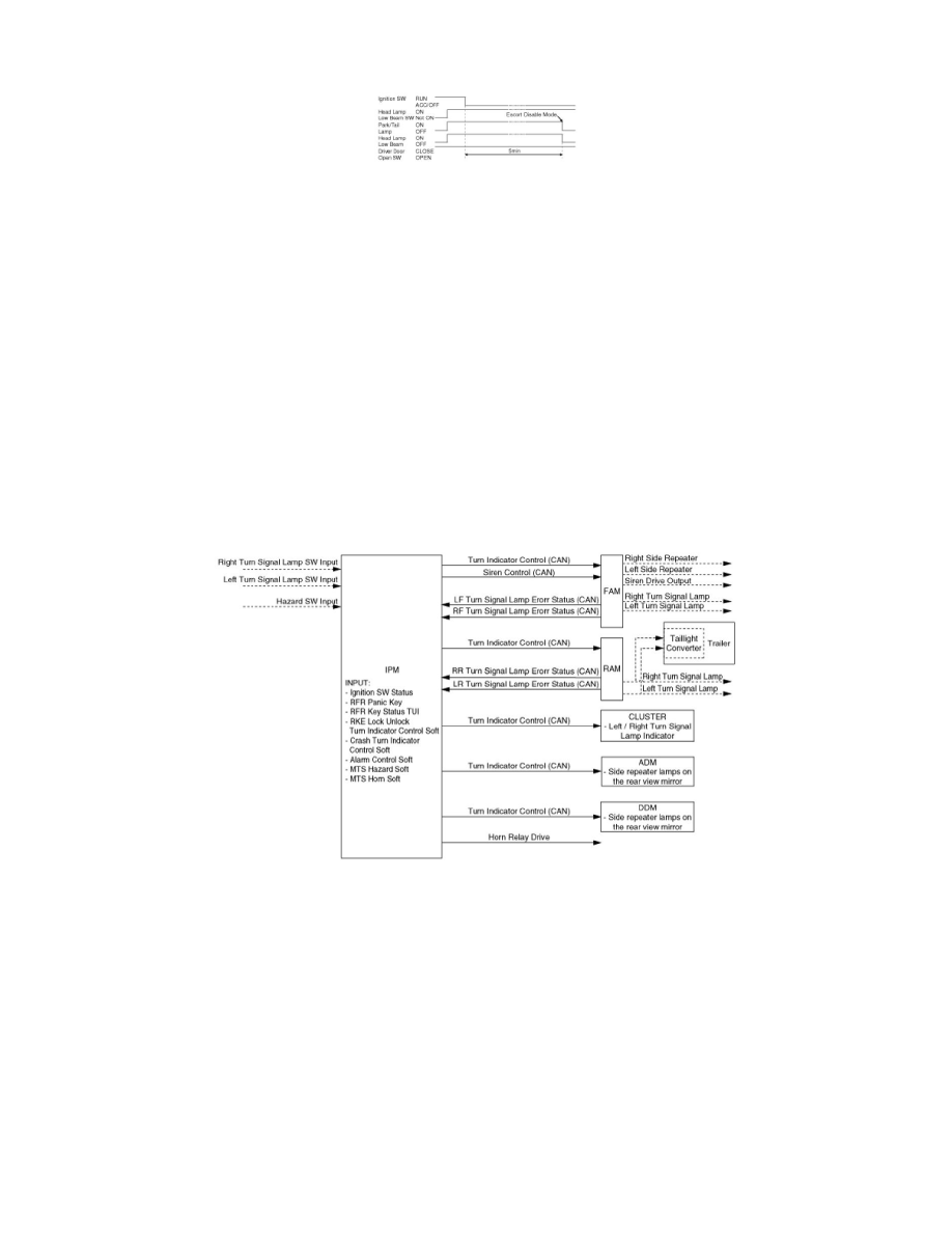
The IPM manages the control logic of the function, and sends the command to the FAM and the RAM that drives the turn signal lamps. The same CAN
signal is used for the front and the rear turn signal activation.
Functional Diagram
IPM
The IPM manages the control logic of the turn signal function. The command of the turn signal lamps is sent to the FAM and the RAM thanks to the
CAN signal Turn Indicator Ctrl, whose values are defined below.
Description
Crash unlock mode:
When a crash unlock occurs, the CAN message Turn Indicator Ctrl is sent with the sequence values all on / all off at the frequency 80 (+/-5) cycles per
minute (duty 50% +/-5%).
Crash unlock sequence stop:
The crash unlock flashing sequence stops when the ignition key is OFF.
Description
Hazard mode: working conditions
The Hazard lamps sequence is activated when the hazard sw input is ON in any position of Ignition Sw.
Description